
Monitoring system of conveyor belt

a monitoring system and conveyor belt technology, applied in the direction of magnetic variables, instruments, transportation and packaging, etc., can solve the problem of not being able to detect statics, and achieve the effects of reducing the limits of magnetic force or the size of the generating means, stable performance, and low cos

Inactive Publication Date: 2010-07-22
BRIDGESTONE CORP
View PDF6 Cites 15 Cited by
  • Summary
  • Abstract
  • Description
  • Claims
  • Application Information

AI Technical Summary

Benefits of technology

[0027]According to the first aspect of the present invention, the magnetic sensor is configured using the MI sensor (magnetic sensor based on the MI effect), and thus it is possible to obtain stable performance with low cost as compared with the case where the magnetic sensor is configured by a Hall element or a loop coil. In addition, limits in the magnetic force or size of the magnetic force generating means are reduced, and thus the degree of freedom in selection of the magnetic force generating means is increased and the degree of freedom in layout is also increased. Accordingly, the degree of freedom of the whole system is improved. Since the magnetic sensor is configured using the MI sensor, it is possible to improve sensitivity in detection of the magnetic force and to improve precision in detecting the condition of the belt.
[0028]When the ground level (output voltage when the external magnetic field is zero) is not set to be 0 V, means for detecting the time when the output of the magnetic sensor is continuously 0 V is provided and thus the sensor can be determined as abnormal within a short time. Accordingly, the system can promptly determine sensor abnormalities, and trouble shooting is rapidly performed.
[0029]According to the second aspect of the present invention, the magnetic sensor is configured using the MI sensor, and a determination means is provided which determines that the magnetic sensor is in an abnormal state when the period of time where the output value of the magnetic sensor deviates from a predetermined range is longer than a predetermined period of time. Accordingly, the system can determine sensor abnormalities, and trouble shooting is rapidly performed.
[0030]According to the third aspect of the present invention, the plurality of magnetic force generating means are provided in the longitudinal direction of the belt, and the interval of time when the magnetic sensor detects the magnetic forces generated by the plurality of magnetic force generating means is calculated to detect the condition of the belt. Accordingly, it is possible to detect that the interval between the magnetic force generating means increases when the interval of time increases, that is, the belt extends.
[0031]According to the fourth aspect of the present invention, the magnetic force generating means is attached to the belt so as to have a regular thickness, the plurality of magnetic sensors are arranged in the widthwise direction of the belt, and the condition of the belt is detected on the basis of the values detected by the magnetic sensors. Accordingly, it is possible to detect that the thickness of the magnetic force generating means is not regular, that is, one-sided abrasion occurs in the belt, when the detected values of the magnetic values and variation thereof with the passage of time fluctuate.
[0032]According to the fifth aspect of the present invention, the magnetic force generating means are separately arranged at least at two parts in the widthwise direction of the belt, the plurality of magnetic sensors are arranged in the widthwise direction of the belt, and the condition of the belt is detected on the basis of the values detected by the magnetic sensors. Accordingly, when it is confirmed that at least two magnetic force generating means are separated from each other from the values detected by the magnetic sensors, it is possible to detect that the gap between the two magnetic force generating means increases, that is, a longitudinal split is about to occur in the belt. In addition, it is possible to perform meandering detection by detecting positional variation of the magnets embedded in the widthwise direction.

Problems solved by technology

The loop coil outputs voltage according to variation in magnetic flux, and thus cannot detect a static magnetic field in which there is no variation in magnetic flux.

Method used


Image

  • Monitoring system of conveyor belt
  • Monitoring system of conveyor belt
  • Monitoring system of conveyor belt

Examples


Embodiment Construction

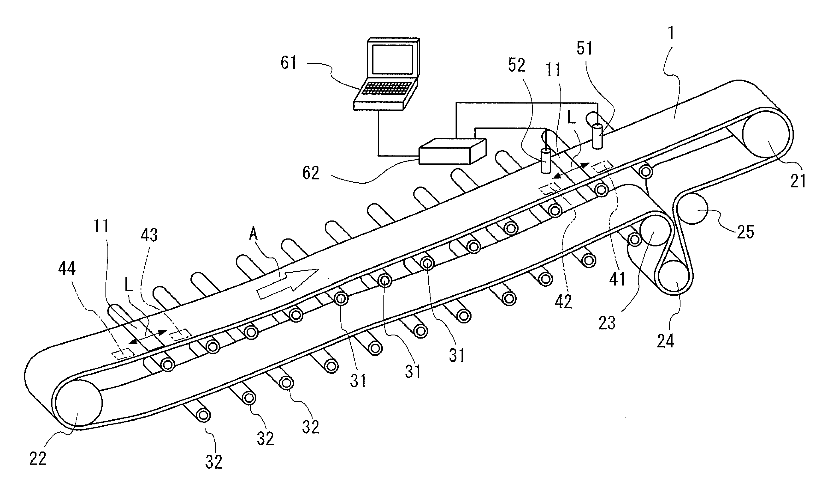
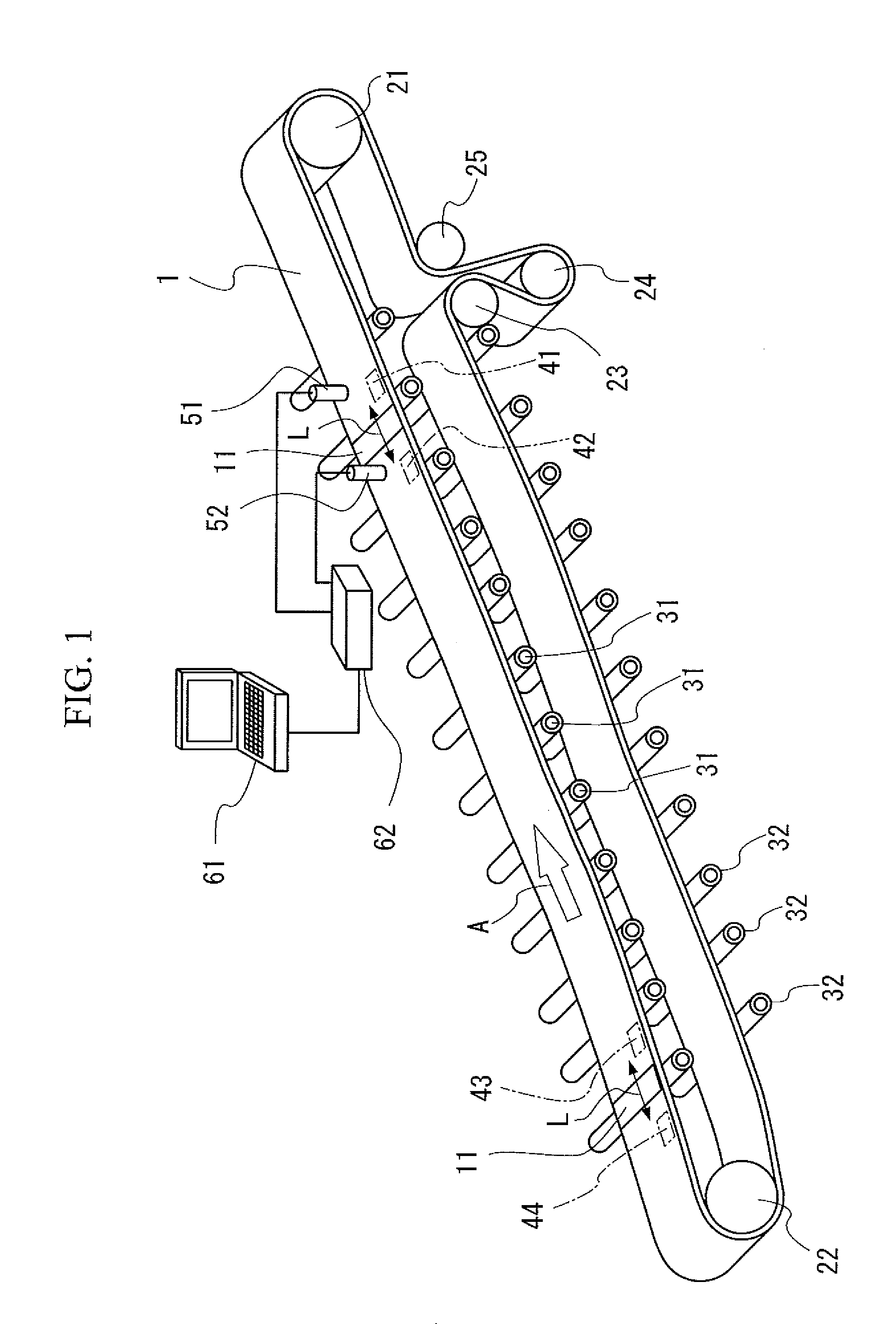
[0064]Hereinafter, embodiments of the present invention will be described with reference to the drawings. FIG. 1 is a schematic view illustrating an appearance of a monitoring system of a conveyor belt according to an embodiment of the present invention.

[0065]As shown in FIG. 1, a conveyor belt 1 (hereinafter, referred to as belt 1) is suspended on a head pulley 21 and a tail pulley 22 provided at both ends, and proceeds in a direction indicated by an arrow A by rotating the head pulley 21 with a motor (not shown) or the like. The belt 1 is provided with a tension device including a bend pulley 23, a tension pulley 24, and a bend pulley 25, to control the tension state. The side of the belt 1 to convey conveyed objects is supported by a plurality of carrier rollers 31, 31, 31, . . . , and the returning side of the belt 1 is supported by a plurality of return rollers 32, 32, 32, . . . .

[0066]Rubber magnets 41 to 44 are embedded in the belt 1. The rubber magnets 41 and 42 are embedded...


PUM


Abstract

A monitoring system including rubber magnets 41 to 44 provided inside of a belt 1, and magnetic sensors 51 and 52 provided outside of the belt 1, and magnetic forces generated by the rubber magnets 41 to 44 are detected by the magnetic sensors 51 and 52, thereby detecting a condition of the belt 1, wherein the magnetic sensors 51 and 52 are configured using MI sensors.

Description

TECHNICAL FIELD[0001]The present invention relates to a monitoring system of a conveyor belt to detect an abnormality of the conveyor belt.[0002]Priority is claimed on Japanese Patent Application No. 2007-187196, the content of which is incorporated herein by reference.BACKGROUND ART[0003]There is a monitoring system (abnormality detecting device) of a conveyor belt in which a belt is provided with a transmission unit that transmits a predetermined signal to detect abnormalities in the belt which is operating, and a reception unit close to the belt receives the transmitted signal, thereby detecting the condition of the belt. In such a system, a magnetic force is generally used for the transmission unit and the reception unit (e.g., Patent Document 1). As a magnetic sensor used for the reception unit, there are many magnetic sensors such as a gauss meter, a Hall element, and a loop coil (e.g., Patent Document 2).[0004]In addition, recently an MI sensor (magnetic impedance sensor) has...

Claims


Application Information

Patent Timeline
Patent Type & Authority Applications(United States)
IPC IPC(8): G01R33/12
CPCB65G43/02B65G2203/043B65G2203/0275B65G2201/0247
Inventor FURUKAWA, KAZUYANISHIKITA, YUKINOBU
Owner BRIDGESTONE CORP
Features
  • Generate Ideas
  • Intellectual Property
  • Life Sciences
  • Materials
  • Tech Scout
  • Unparalleled Data Quality
  • Higher Quality Content
  • 60% Fewer Hallucinations
Learn More