Methods and systems for storing and accessing data in uas based flash-memory device

a flash memory and data storage technology, applied in the field of flash memory devices, can solve the problems of limited writing, bridges are often slow, legacy host systems are not equipped for the newer bus protocol,

Active Publication Date: 2010-07-22
SUPER TALENT TECH CORP
View PDF42 Cites 112 Cited by
  • Summary
  • Abstract
  • Description
  • Claims
  • Application Information

AI Technical Summary

Benefits of technology

[0034]According to yet another aspect, security module/engine/unit in the EUSB device's controller is configured for authenticating user of the device. To enable such feature, the EUSB device is manufactured with at least two partitions in its flash memory arrays, one for storing public data with another for storing read-only files that triggers an automated authentication procedure. For example, the read-only partition is formatted as Compact Disc File System (CDFS) with “autorun.inf” file stored thereon. Upon detecting the CDFS partition after the EUSB device is connected to EUSB host, an authentication session starts in accordance with instructions set forth in “autorun.inf”. Within the authentication session, a number of scenarios are conducted. In one

Problems solved by technology

Pages in the same block may have to be erased together, and limitations on writing may exist, such as only being allowed to write each page once between erases.
Legacy host systems are not equipped for the newer bus protocols since these legacy systems are older and were designed before the new bus

Method used


Image

  • Methods and systems for storing and accessing data in uas based flash-memory device
  • Methods and systems for storing and accessing data in uas based flash-memory device
  • Methods and systems for storing and accessing data in uas based flash-memory device

Examples


Embodiment Construction

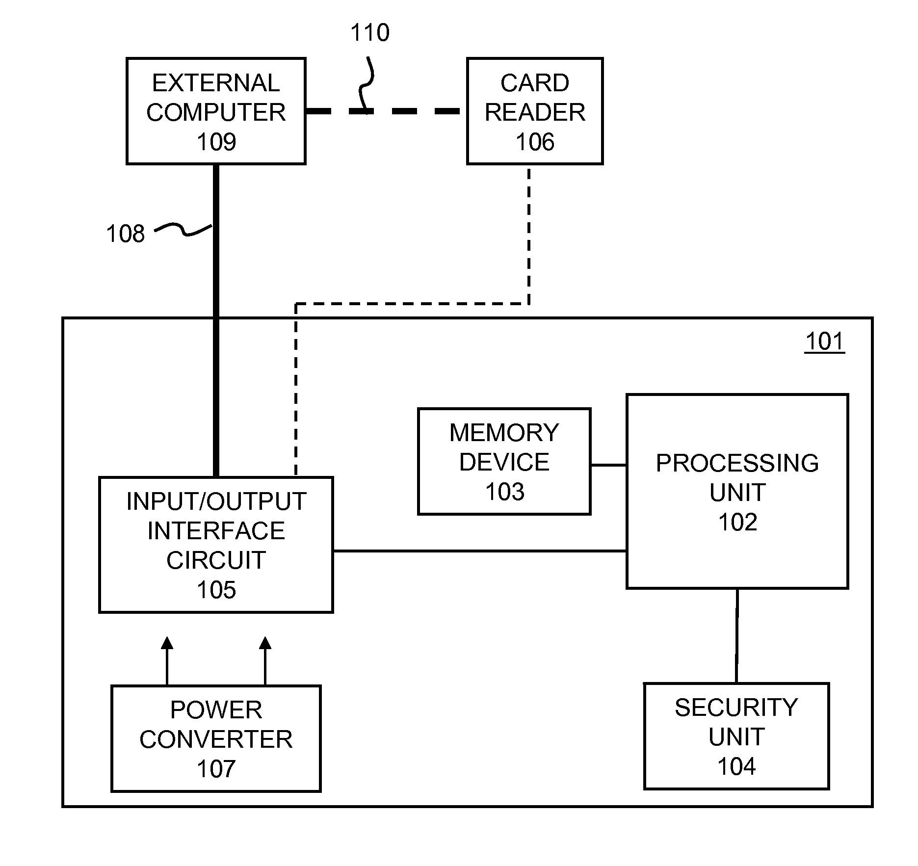
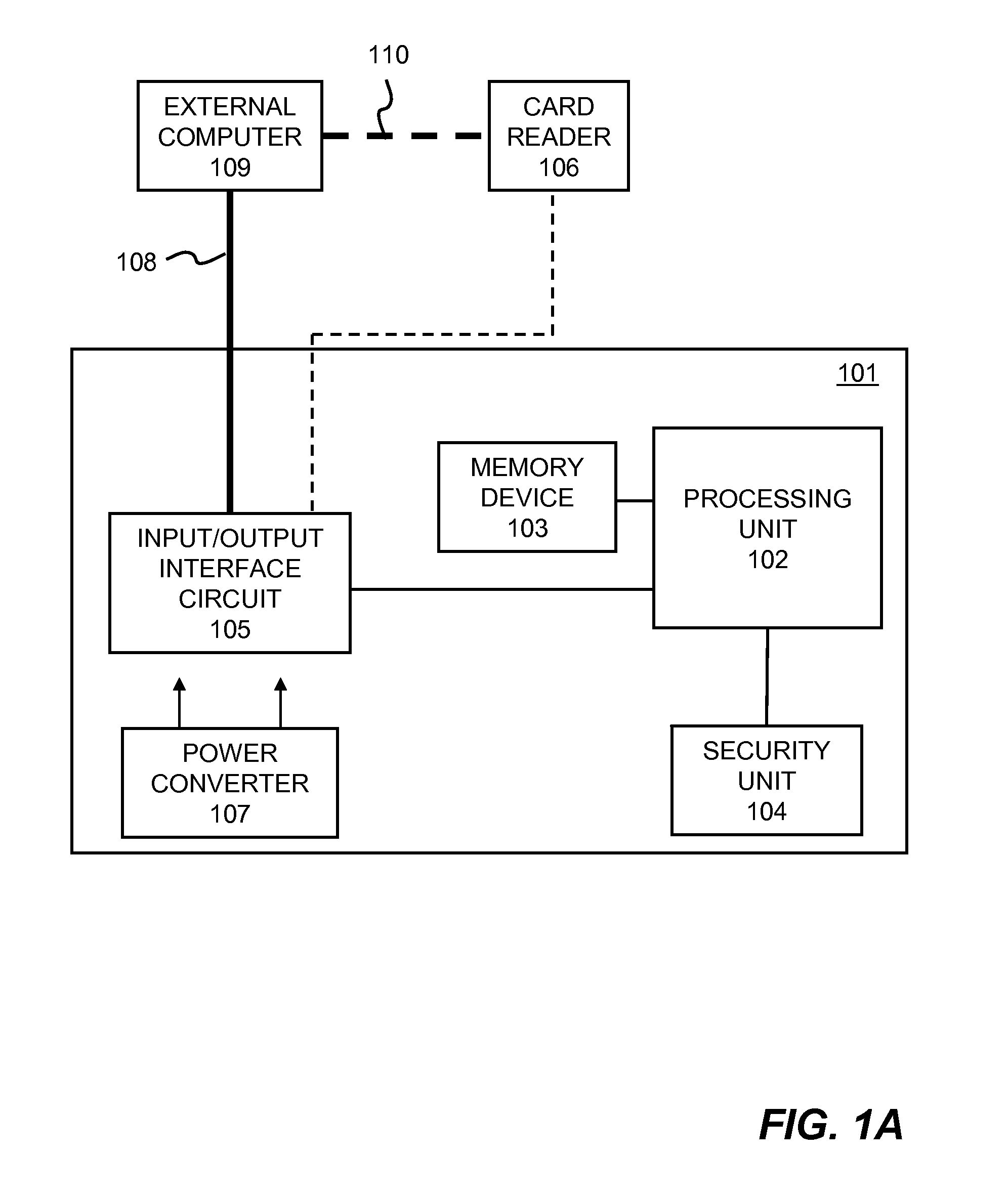
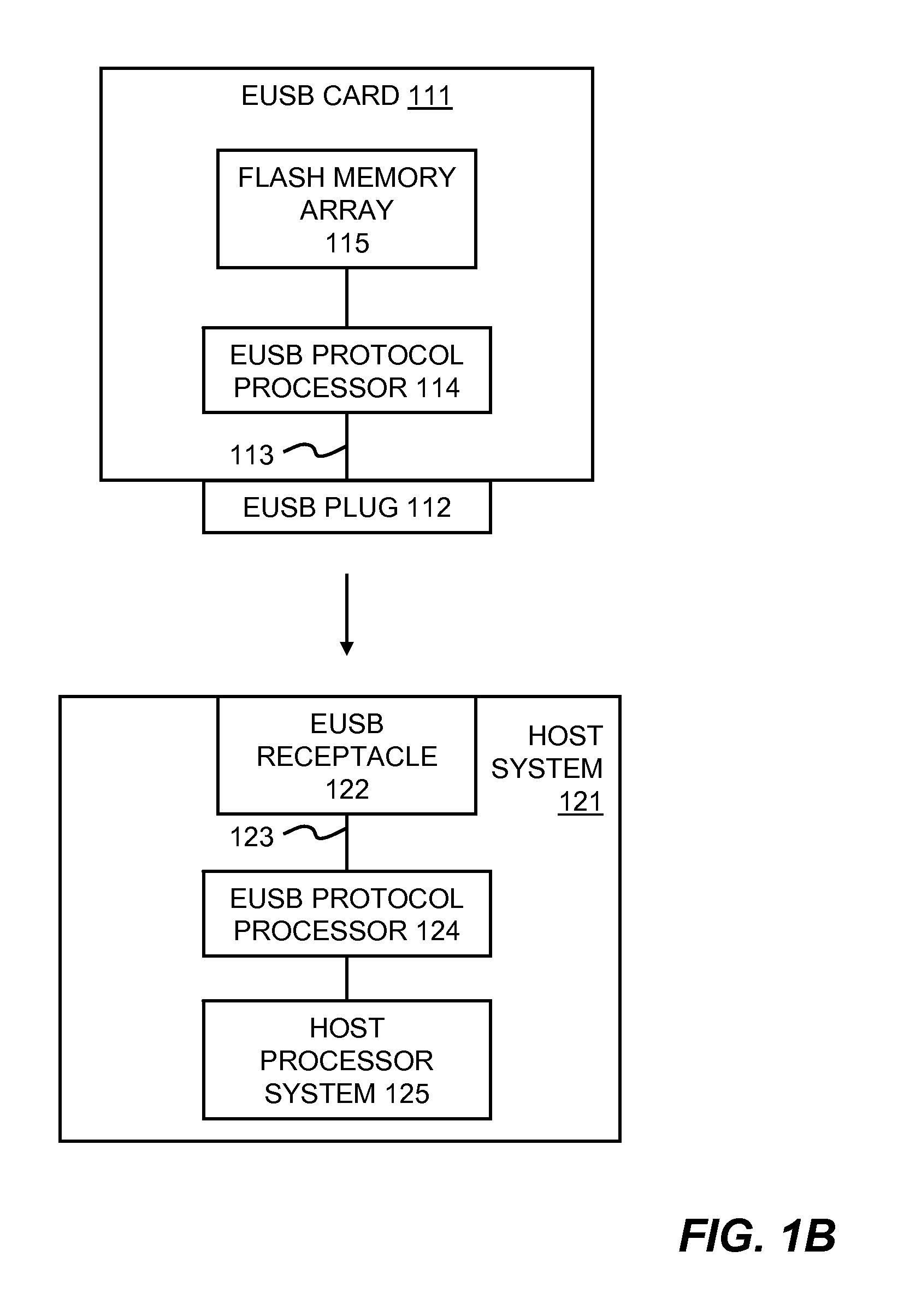
[0081]In the following description, numerous details are set forth to provide a more thorough explanation of embodiments of the present invention. It will be apparent, however, to one skilled in the art, that embodiments of the present invention may be practiced without these specific details. In other instances, well-known structures and devices are shown in block diagram form, rather than in detail, in order to avoid obscuring embodiments of the present invention.

[0082]Reference herein to “one embodiment” or “an embodiment” means that a particular feature, structure, or characteristic described in connection with the embodiment can be included in at least one embodiment of the invention. The appearances of the phrase “in one embodiment” in various places in the specification are not necessarily all referring to the same embodiment, nor are separate or alternative embodiments mutually exclusive of other embodiments. Further, the order of blocks in process flowcharts or diagrams rep...


PUM


Abstract

Methods and systems for storing and accessing data in UAS based flash memory device are disclosed. UAS based flash memory device comprises a controller and a plurality of non-volatile memories (e.g., flash memory) it controls. Controller is configured for connecting to a UAS host via a physical layer (e.g., plug and wire based on USB 3.0) and for conducting data transfer operations via two sets of logical pipes. Controller further comprises a random-access-memory (RAM) buffer configured for enabling parallel and duplex data transfer operations through the sets of logical pipes. In addition, a Smart Storage Switch configured for connecting multiple non-volatile memory devices is included in the controller. Finally, a security module/engine/unit is provided for data security via user authentication data encryption/decryption of the device. Furthermore, the flash memory device includes an optical transceiver configured for optical connection to a host also configured with an optical transceiver.

Description

CROSS REFERENCE TO RELATED APPLICATIONS[0001]This application is a continuation-in-part (CIP) of co-pending U.S. patent application Ser. No. 12 / 254,428 for “PCI EXPRESS-COMPATIBLE CONTROLLER AND INTERFACE FOR FLASH MEMORY”, filed on Oct. 20, 2008, which is a divisional application of U.S. patent application Ser. No. 10 / 803,597 for the same title, filed on Mar. 17, 2004, now U.S. Pat. No. 7,457,897.[0002]This application is also a CIP of “EXTENDED SECURE-DIGITAL (SD) DEVICES AND HOSTS”, U.S. application Ser. No. 10 / 854,004, filed on May 25, 2004.[0003]This application is also a CIP of “Flash-Memory System with Enhanced Smart-Storage Switch and Packed Meta-Data Cache for Mitigating Write Amplification by Delaying and Merging Writes until a Host Read” U.S. application Ser. No. 12 / 576,216, filed on Oct. 8, 2009.[0004]This application is also a CIP of “Secure Flash-Memory Card Reader with Host-Encrypted Data on a Flash-Controller-Mastered Bus Parallel to a Local CPU Bus Carrying Encrypte...

Claims


Application Information

Patent Timeline
IPC IPC(8): G06F12/02G06F13/36G06F12/14G06F13/00
CPCG06F13/1684G11C16/102G11C2216/30
Inventor YU, I-KANGLEE, CHARLES C.CHEN, SHIMONMA, ABRAHAM C.
Owner SUPER TALENT TECH CORP
Why Eureka
Try Eureka