Shift register circuit having threshold voltage compensation

a register circuit and threshold voltage technology, applied in the field of shift register circuits, can solve the problems of increasing the lifespan of the circuit, serious difficulties in implementing driver circuit and losing the cost advantage of producing display arrays using amorphous silicon technology

Inactive Publication Date: 2010-07-29
KONINKLIJKE PHILIPS ELECTRONICS NV
View PDF2 Cites 65 Cited by
  • Summary
  • Abstract
  • Description
  • Claims
  • Application Information

AI Technical Summary

Benefits of technology

[0023]Leakage current control circuitry can also be provided for controlling the direction of flow or magnitude of leakage current to or from the gate of the at least one of the pull up and pull down transistors, connected between the gate of the at least one of the pull up and pull down transistors and a power supply line. This can be used to stabilize the stored threshold voltage over time, or ensure that the effect of the compensation is not reduced over time.

Problems solved by technology

The cost advantages of producing the display array using amorphous silicon technology are then lost.
The low mobility of amorphous silicon transistors, as well as the stress-induced change (drift) in threshold voltage, present serious difficulties in implementing driver circuits using amorphous silicon technology.
This in turn gives rise to an increased lifespan for the circuit.
There remains a problem with the known circuits that degradation of transistor performance, particularly for transistors that are operated with a high duty cycle and therefore normally on, limits the lifetime of the circuit.

Method used


Image

  • Shift register circuit having threshold voltage compensation
  • Shift register circuit having threshold voltage compensation
  • Shift register circuit having threshold voltage compensation

Examples


Embodiment Construction

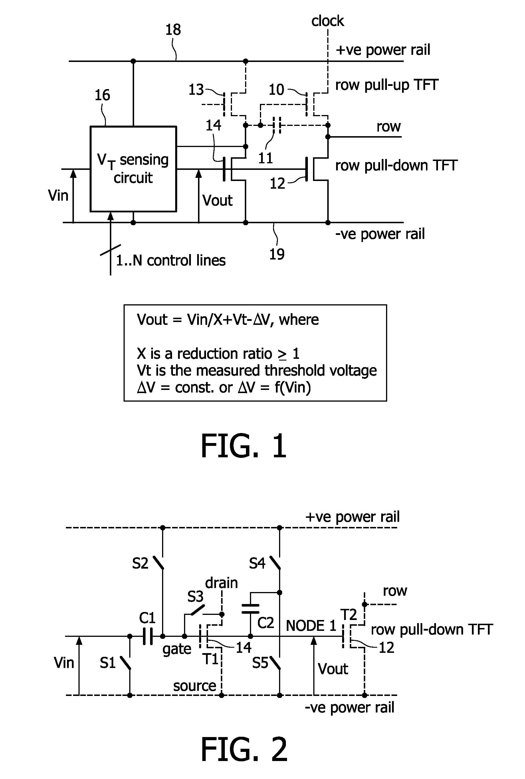
[0061]FIG. 1 shows a first simplified example of circuit of the invention to illustrate the principles of the invention.

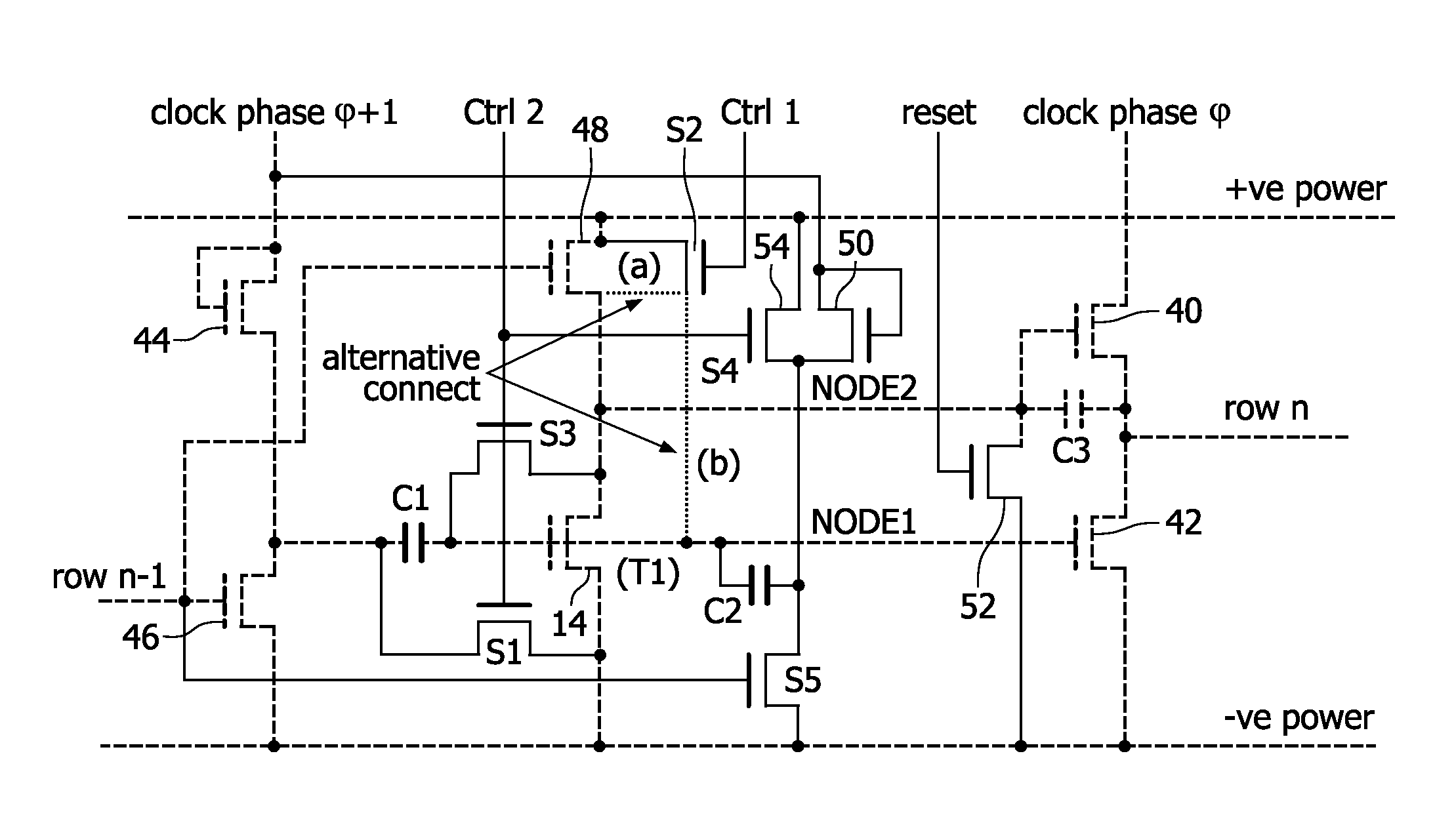
[0062]The invention provides sensing of the threshold voltage of the most critical transistor or transistors in the circuit. The row driver circuit has a row pull-up transistor 10, which is turned on to provide a row pulse on the row from a clocked power supply line “clock”, and a row pull-down transistor 12 for holding the row at a low negative power rail voltage for the remainder of the time. The row pull-down transistor 12 is operated with a high duty cycle and therefore suffers greatest drift.

[0063]In one example, the invention provides threshold voltage sensing of the row pull down transistor 12. The sensing circuit may use the thin film transistor (TFT) of the row driver circuit, or it may use a dedicated TFT which is designed to match the characteristics of the TFT being compensated.

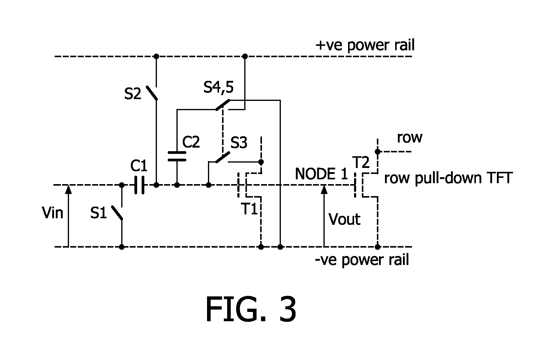
[0064]FIG. 1 shows a transistor 14 used to replicate the conditions of the p...


PUM


Abstract

A shift register circuit comprises a plurality of stages, each stage being for providing an output signal to an output load and comprising a pull up transistor for pulling the output signal up to a high voltage rail and a pull down transistor for pulling the output signal down to a low voltage rail. Each stage comprises a circuit for sampling the threshold voltage of at least one of the pull up and pull down transistors and for adding the sampled threshold voltage to a control voltage offset, to provide a threshold-voltage-compensated signal for controlling the gate of the at least one of the pull up and pull down transistors. This provides threshold voltage sampling, in particular for the thin film transistor whose threshold voltage drift must be compensated (for example the pull-down thin film transistor).

Description

FIELD OF THE INVENTION[0001]The invention relates to a shift register circuit, in particular for providing the row voltages to the display pixels of an active matrix display device.BACKGROUND OF THE INVENTION[0002]Active matrix display devices comprise an array of pixels arranged in rows and columns, and each comprising at least one thin film drive transistor and a display element, for example a liquid crystal cell. Each row of pixels shares a row conductor, which connects to the gates of the thin film transistors of the pixels in the row. Each column of pixels shares a column conductor, to which pixel drive signals are provided. The signal on the row conductor determines whether the transistor is turned on or off, and when the transistor is turned on (by a high voltage pulse on the row conductor) a signal from the column conductor is allowed to pass on to an area of liquid crystal material, thereby altering the light transmission characteristics of the material.[0003]The frame (fie...

Claims


Application Information

Patent Timeline
Patent Type & Authority Applications(United States)
IPC IPC(8): G09G5/00G11C19/18G09G3/36
CPCG11C19/184G09G3/3677
Inventor BOIKO, EVGUENI
Owner KONINKLIJKE PHILIPS ELECTRONICS NV
Why Eureka
Try Eureka