
Compensation of propagation delays of wireless signals

a technology of wireless signals and offsets, applied in the field of wireless communication, can solve the problems of affecting timing delay and arising wireless signal path propagation delay, and achieve the effects of reducing the magnitude of propagation delay error, reducing the error in location determination, and reducing the error in location fix

Active Publication Date: 2010-07-29
AT&T MOBILITY II LLC
View PDF59 Cites 310 Cited by
  • Summary
  • Abstract
  • Description
  • Claims
  • Application Information

AI Technical Summary

Benefits of technology

[0006]At least two advantages of the system(s) and method(s) of the subject innovation and aspects therein are (i) substantially reduced magnitude of the error for propagation delay used in “time of flight” calculations by several position determination functions (PDFs), and associated component(s) for implementation thereof, in wireless location services. As an example, for a representative Global System for Mobile Communications (GSM) or Universal Mobile Telecommunications System (UMTS) base station without distributed antenna system (DAS), the error in location determination can be reduced by as much as several hundred meters when compensation for wireless signal timing variation is included as described herein. It is noted that for a wireless environment served, at least in part, through a DAS the error in location fix can be reduced by as much or even more than 1000 meters. Accordingly, the system(s), method(s), and aspects thereof described herein improve the accuracy of TOF location estimates with respect to estimates provided by conventional systems that ignore, or fail to incorporate, propagation delay in estimation of timing advance (TA) or round trip time (RTT), or any time of flight quantities utilized to estimate location(s) in operational wireless systems. (ii) Improvement(s) in radio network performance that results, for example, from accurate timing in FL (forward link) signaling (e.g., pilot sequence(s)) which can facilitate cell search or synchronization, or handover. In addition, calibrated signal timing delay can provide accuracy in location estimates that allows utilization of location data as a metric to generate, at least in part, lists of candidate Node Bs for handover, or establish criteria (e.g., handover occurs when a mobile device is within a specific time-delay band) for handover from a confined coverage cell, e.g., a femtocell, to macrocell coverage.

Problems solved by technology

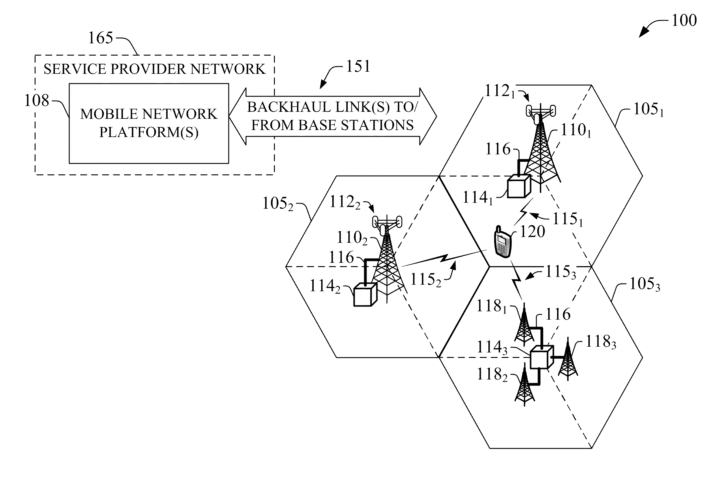
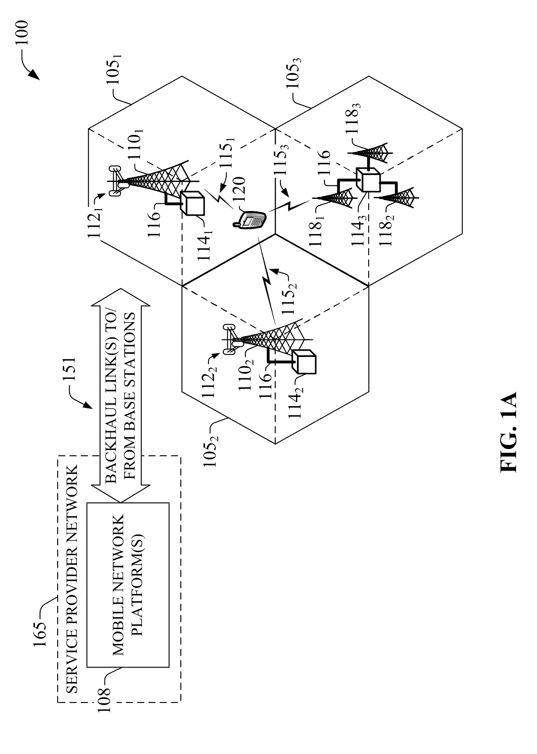
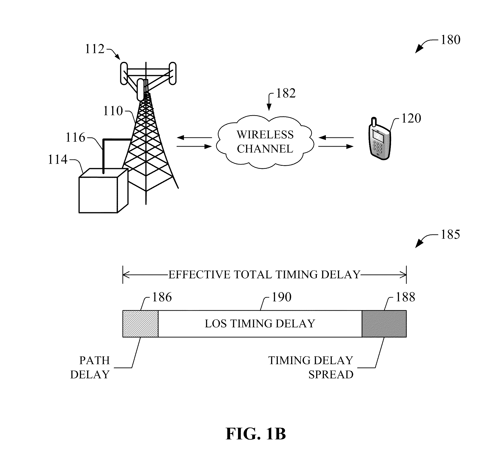
Timing delay is affected by propagation delay in the wireless signal path among radio component(s) at the wireless base station and a sector antenna.
Wireless signal path propagation delay can arise from various mismatches (e.g., impedance mismatch) among electronic elements and components, stray capacitances and inductances, length of the antenna(s) cable(s) in base station(s); tower height of base station, any signal path scattering, or “signal bounces,” such as multipath or strong reflections, etc.

Method used


Image

  • Compensation of propagation delays of wireless signals
  • Compensation of propagation delays of wireless signals
  • Compensation of propagation delays of wireless signals

Examples


embodiment 1000

[0069]FIG. 10 illustrates a block diagram of an example embodiment of an access point to implement and exploit one or more features or aspects of the subject innovation. In embodiment 1000, AP 1005 can receive and transmit signal(s) (e.g., attachment signaling) from and to wireless devices like femto access points, access terminals, wireless ports and routers, or the like, through a set of antennas 10201-1020N (N is a positive integer). It should be appreciated that antennas 10201-1020N embody antenna(s) 232, and are a part of communication platform 1015, which comprises electronic components and associated circuitry that provides for processing and manipulation of received signal(s) and signal(s) to be transmitted. Such electronic components and circuitry embody at least in part signaling and traffic component 234; communication platform 1015 operates in substantially the same manner as communication platform 230 described hereinbefore. In an aspect, communication platform 1015 inc...

embodiment 1100

[0075]In embodiment 1100, wireless network platform 1110 also includes serving node(s) 1116 that, based upon available radio technology layer(s) within technology resource(s) 1117, convey the various packetized flows of data streams received through PS gateway node(s) 1118. It is to be noted that for technology resource(s) 1117 that rely primarily on CS communication, server node(s) can deliver traffic without reliance on PS gateway node(s) 1118; for example, server node(s) can embody at least in part a mobile switching center. As an example, in a 3GPP UMTS network, serving node(s) 1116 can be embodied in serving GPRS support node(s) (SGSN).

[0076]For radio technologies that exploit packetized communication, server(s) 1114 in mobile, or wireless, network platform 1110 can execute numerous applications (e.g., location services, online gaming, wireless banking, wireless device management . . . ) that can generate multiple disparate packetized data streams or flows, and manage (e.g., sc...


PUM


Abstract

System(s) and method(s) for compensation of propagation delay offsets of wireless signals. Compensation is accomplished through determination of an effective wireless signal propagation delay that accounts for signal path delay and propagation delay over the air. Such determination is based at least in part on statistical analysis of accurate location estimates of reference positions throughout a coverage sector or cell, and location estimates of the reference positions generated through time-of-flight (TOF) measurements of wireless signals. Determination of propagation or signal path delay offset also is attained iteratively based at least in part on reference location estimates and TOF location estimates. High-accuracy location estimates such as those obtained through global navigation satellite systems are employed as reference location estimates. Position of probes or wireless beacons, deployed throughout a sector or cell, also are employed as reference locations. Compensation of propagation delay offset improves accuracy of conventional TOF location estimates and radio network performance.

Description

CROSS-REFERENCE TO RELATED APPLICATIONS[0001]This application claims the benefit of U.S. Provisional Application Ser. No. 61 / 146,997 filed on Jan. 23, 2009, entitled “COMPENSATION OF PROPAGATION DELAYS OF WIRELESS SIGNALS.” The entirety of this provisional application is incorporated herein by reference.TECHNICAL FIELD[0002]The subject innovation relates to wireless communications and, more particularly, to correction of propagation delay offsets of wireless signals.BACKGROUND[0003]In mobile networks, timing delay of the signals transmitted between the wireless base station and the wireless handset are employed in various location services methods, including, but not limited to, cell global identity and timing advance (CGI+TA), CGI and round trip time (CGI+RTT), time of arrival (TOA), and custom methods. Timing delay is affected by propagation delay in the wireless signal path among radio component(s) at the wireless base station and a sector antenna. Wireless signal path propagatio...

Claims


Application Information

Patent Timeline
IPC IPC(8): H04W64/00H04W4/02
CPCH04W4/02H04W56/006
Inventor DAVIS, RICHARD W.
Owner AT&T MOBILITY II LLC
Learn More