Biological information processing apparatus and biological information processing method

Inactive Publication Date: 2010-07-29
CANON KK
View PDF16 Cites 64 Cited by
  • Summary
  • Abstract
  • Description
  • Claims
  • Application Information

AI Technical Summary

Benefits of technology

[0014]According to the present invention, in photoacoustic tomography, it is possible to ob

Problems solved by technology

However, because the light introduced in the test object (in particular, the living body) is d

Method used


Image

  • Biological information processing apparatus and biological information processing method
  • Biological information processing apparatus and biological information processing method
  • Biological information processing apparatus and biological information processing method

Examples


Example

First Embodiment

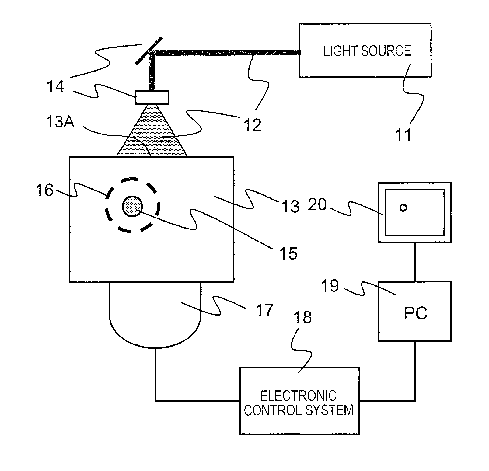
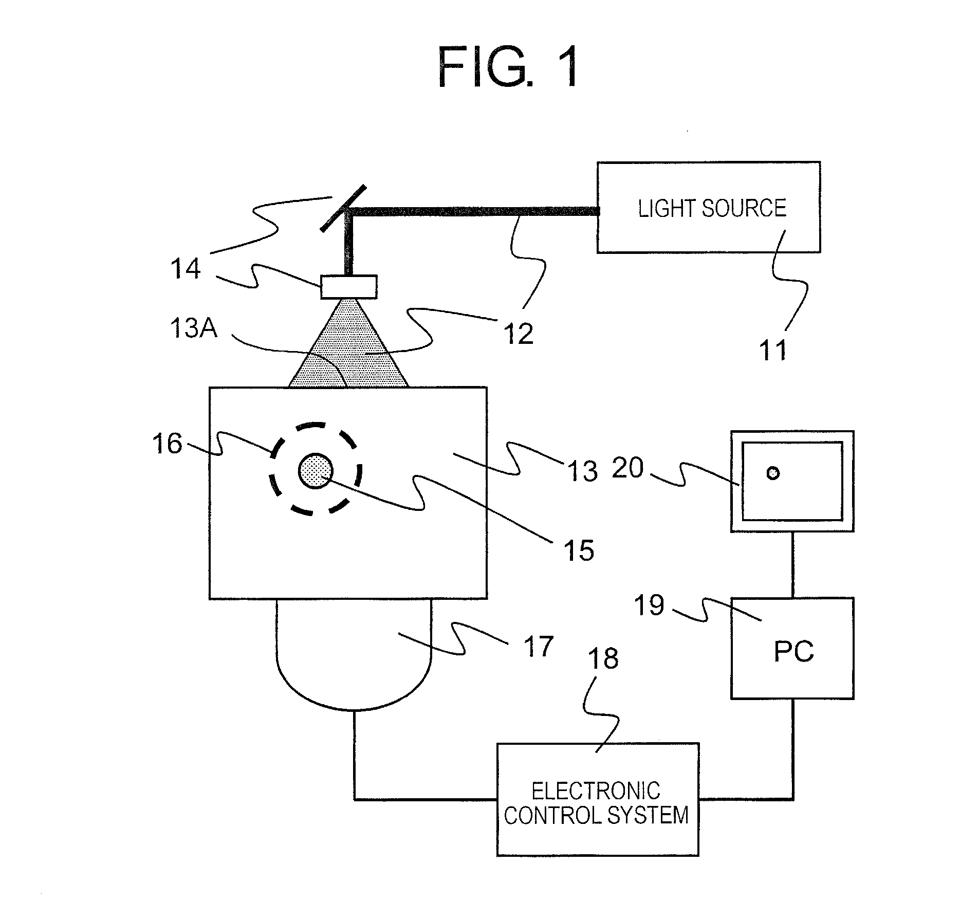
[0032]FIG. 1 shows the construction of a biological information imaging apparatus in a first embodiment of the present invention. Now, the first embodiment of the present invention will be described based on FIG. 1. The biological information processing apparatus to be described here is a biological information processing apparatus which makes it possible to image an optical property distribution in a living body and a concentration distribution of substances that constitute a living body tissue obtained from these information, for the purposes of diagnosis of a malignant tumor, a vascular disease, etc., and of the follow-up of a chemical treatment, etc.

[0033]The biological information processing apparatus is composed of a light source 11, an optical device 14, an acoustic wave detector (also referred to as a probe) 17, an electronic control system 18, a signal processing device 19, and a display device 20. The light source 11 is a device that emits light 12. The opt...

Example

Second Embodiment

[0058]In a second embodiment, reference will be made to a construction example in which an absorption coefficient distribution in the form of an optical property distribution is calculated from temporal change information of sound pressure obtained in cases where light irradiation is carried out in the same direction as the location of an acoustic wave detector.

[0059]FIG. 5A illustrates a view explaining a construction example of a biological information processing apparatus in this embodiment. For the purpose of diagnosing various diseases such as malignant tumors, Alzheimer's disease, carotid artery plaque, etc., by the use of a contrast medium, the biological information processing apparatus of this embodiment serves to make it possible to image the accumulated place or location of the contrast medium introduced into a living body, and concentration distributions therein.

[0060]The biological information processing apparatus is provided with a light source 51, an ...

Example

Third Embodiment

[0064]In the first embodiment, light is irradiated to a region which is sufficiently larger than an imaging region, so it is assumed that light propagates through the interior of the test object like a plane wave. In this embodiment, however, it is presented that even in cases where such an assumption does not hold, the gain of the amplifier is controlled based on a fluence distribution in a living body.

[0065]In this embodiment, a step of calculating or determining a fluence distribution in a test object, and a step of determining a change in the gain of the above-mentioned amplifier with respect to the detection time of an acoustic wave in each element of an ultrasonic detector based on the fluence distribution are carried out.

[0066]A specific embodiment will be described by using FIG. 7, FIG. 8A through FIG. 8D, and FIG. 9. FIG. 7 is a biological information processing apparatus showing an example of a third embodiment of the present invention. A light source and a...


PUM


Abstract

A biological information processing apparatus includes: a light source 11 that irradiates light 12 to a light irradiation region 13A on a test object 13; an acoustic wave detector 17 that detects an acoustic wave 16 generated by a light absorber 15 in the test object upon its absorption of the light, and outputs a detection signal; and an electronic control system 18 having an amplifier that amplifies the detection signal outputted from the acoustic wave detector 17. The electronic control system controls a gain of the amplifier in such a manner that a gain for a detection signal of an acoustic wave generated at a first location in the test object becomes larger as compared with a gain for a detection signal of an acoustic wave generated at a second location which exists nearer to the light irradiation region than the first location does.

Description

BACKGROUND OF THE INVENTION[0001]1. Field of the Invention[0002]The present invention relates to a biological information processing apparatus and a biological information processing method.[0003]2. Description of the Related Art[0004]In general, many imaging apparatuses using X-rays, ultrasonic waves, and MRI (nuclear magnetic resonance imaging) are used in the medical field. On the other hand, in the medical field, studies are being positively carried out on an optical imaging apparatus which obtains information in a living body by causing a beam of light irradiated from a light source such as a laser to propagate in a test object such as a living body, and detecting the propagation light or the like. As one of such optical imaging techniques, there has been proposed photoacoustic tomography (PAT) (Non Patent Literature 1).[0005]The PTA is a technique in which a test object is irradiated with pulsed light generated from a light source, and acoustic waves generated from a living bo...

Claims


Application Information

Patent Timeline
IPC IPC(8): A61B8/00
CPCA61B5/0059A61B5/0095G01N2021/1706A61B8/0833G01N21/1702A61B8/00
Inventor FUKUTANI, KAZUHIKONAKAJIMA, TAKAOBABA, YOSHITAKA
Owner CANON KK
Why Eureka
Try Eureka