[0002]In the prior art, for various purposes, fixed vacuum capacitors with a certain
capacitance and variable vacuum capacitors with a capacitance that is adjustable within a certain range are used. Vacuum capacitors may be used in broadcast systems, in systems for the production of
flat panel displays or semiconductors, or in other industrial applications. Vacuum as a
dielectric medium offers many advantages. Because of the high
dielectric strength, it is possible to maintain very close plate spacing and still have a capacitor with good
high voltage capabilities. Should a breakdown occur in a vacuum capacitor, this does not normally result in permanent damage which is often the case with capacitors with other dielectrics, such as paper, SF6, or other dielectrics. Variable vacuum capacitors often comprise a first
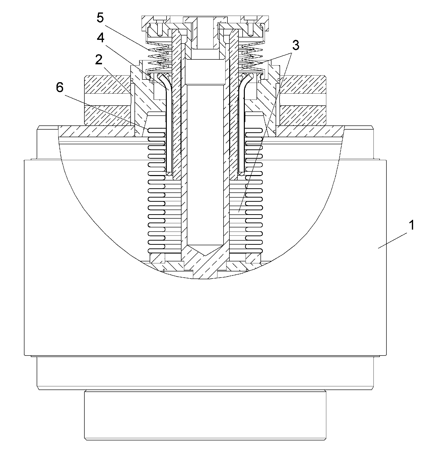
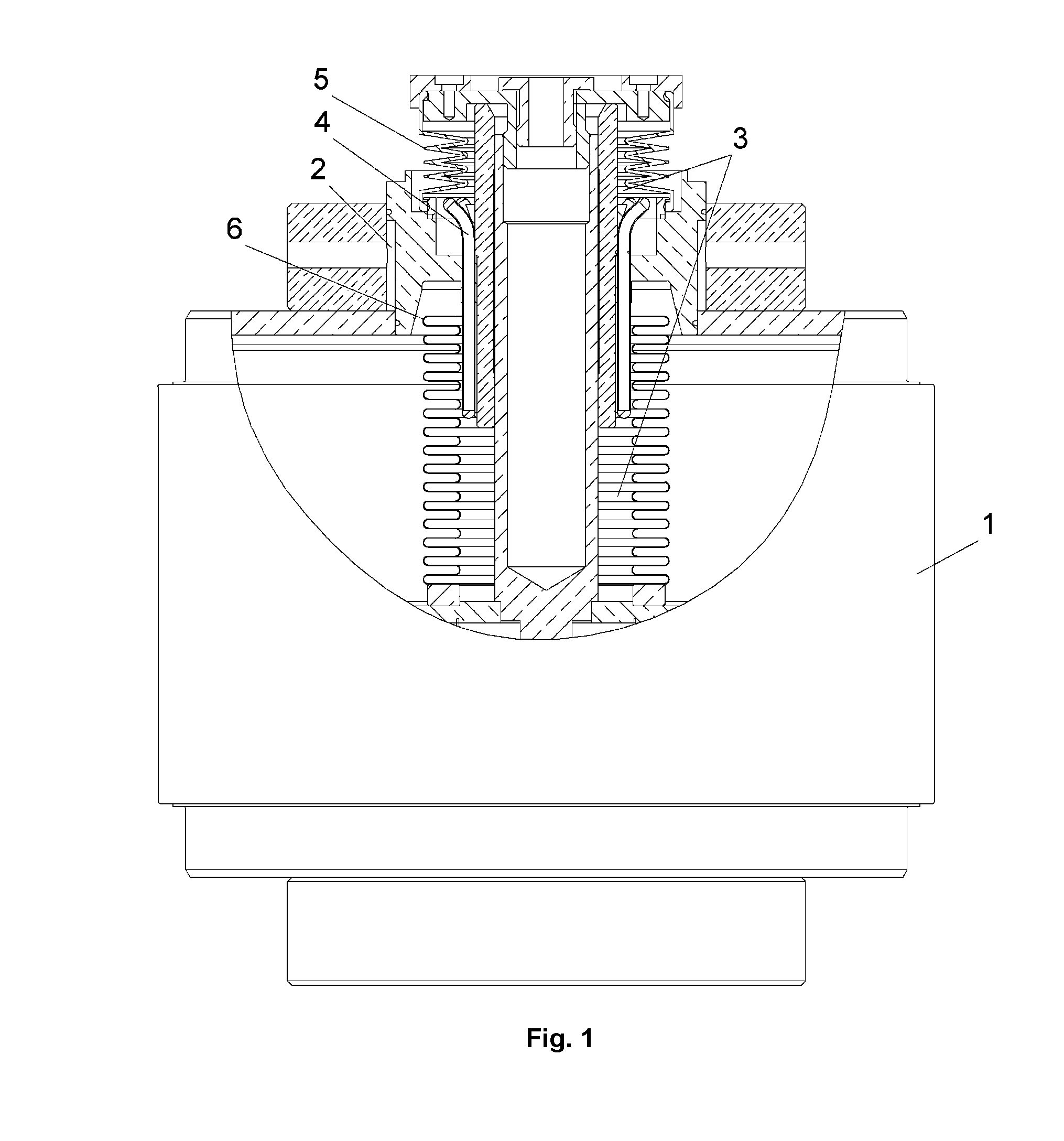
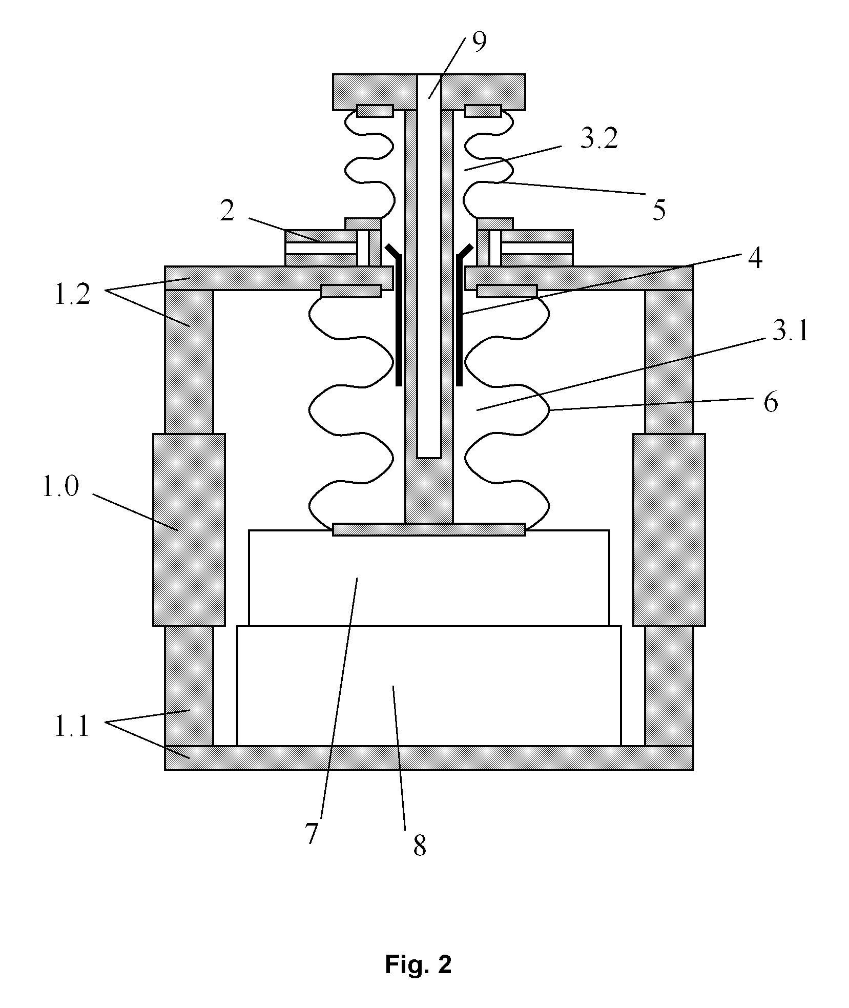
electrode that, by means of a
metal bellows, is movably arranged with respect to a first part of the housing of the variable vacuum capacitor. An insulator is tightly connected between the first part of the housing and the second part of the housing. The second part of the housing comprises a second electrode. A vacuum that extends between the first electrode and the second electrode is established inside the housing. With such an arrangement, a
variable capacitor is established, wherein the capacitance of the
variable capacitor depends on the distance between the first, movably arranged electrode and the second electrode. When such a variable vacuum capacitor is in use, electrical energy is transmitted over the
metal bellows between the first part of the housing and the first electrode. The
metal bellows has to be flexible enough to allow a smooth movement of the first electrode and, as well, the
metal bellows has to be a good
electrical conductor. However, these requirements are difficult to achieve at the same time. Therefore, when such a variable vacuum capacitor is used in
high energy applications, excessive heat energy may be produced in the metal bellows. In prior art,
water cooling systems have been used to provide a sufficient cooling of a variable vacuum capacitor. In the document CH656740, a turbulence
water cooling system with a high efficiency is described.
Water cooling systems are arranged such that a water
stream is guided inside the metal bellows, thus enabling an efficient cooling of the metal bellows. A drawback of a water cooling system is that distilled or de-ionized water has to be used. Moreover, the water purity and flow protection should be periodically checked to insure against excessive degradation. Water purity can be seriously degraded by contaminants from the various cooling system components. For example, free
oxygen and
carbon dioxide in the
coolant will form
copper oxide on the surfaces, thereby reducing the
cooling efficiency. Moreover, if a
water cooled vacuum capacitor is not used for a certain time period, a complicated
drying procedure has to be applied first, in order to avoid
corrosion.

