Multiple beam laser system for forming stents

a laser system and multi-beam technology, applied in laser beam welding apparatus, manufacturing tools, catheters, etc., can solve the problems of reducing the cutting efficiency of lasers, reoccurring constrictions or blockages, and exacerbate the occurrence of restenosis or thrombosis, so as to improve cutting quality and efficiency.

Inactive Publication Date: 2010-08-05
ABBOTT CARDIOVASCULAR
View PDF87 Cites 24 Cited by
  • Summary
  • Abstract
  • Description
  • Claims
  • Application Information

AI Technical Summary

Benefits of technology

[0020]The present invention is directed to an optical design for a multiple beam laser system. The various aspects of the present invention are an improvement over previously developed multiple beam laser systems because circular polarization is introduced to the laser beam after the beam reflects from the last mirror in the optical path. As a result, the cutting laser beam is maximally circular rather than elliptical or linear, which improves the cutting quality and efficiency for a multi-directional cutting pattern, such as is cut into a stent.

Problems solved by technology

Although the stents are effective in opening the stenotic lumen, the foreign material and structure of the stents themselves may exacerbate the occurrence of restenosis or thrombosis.
Although PTCA and related procedures aid in alleviating intraluminal constrictions, such constrictions or blockages reoccur in many cases.
Such systems, however, must employ complex optical systems that, if not properly aligned, may reduce the cutting efficiency of the laser.
However, the phases for s and p polarized beams are not controlled.
Such elliptically polarized laser beams have been found to be less efficient at cutting multi-directional patterns, such as are cut into stents.
This problem is further aggravated by polarization shifts induced when the laser beam travels through beam splitting mirrors.
As a result, tuning of the cutting laser beam is difficult because adjustment of one cutting laser beam polarization to an ideal state will necessarily adjust another laser beam to non-ideal state.

Method used


Image

  • Multiple beam laser system for forming stents
  • Multiple beam laser system for forming stents
  • Multiple beam laser system for forming stents

Examples


Embodiment Construction

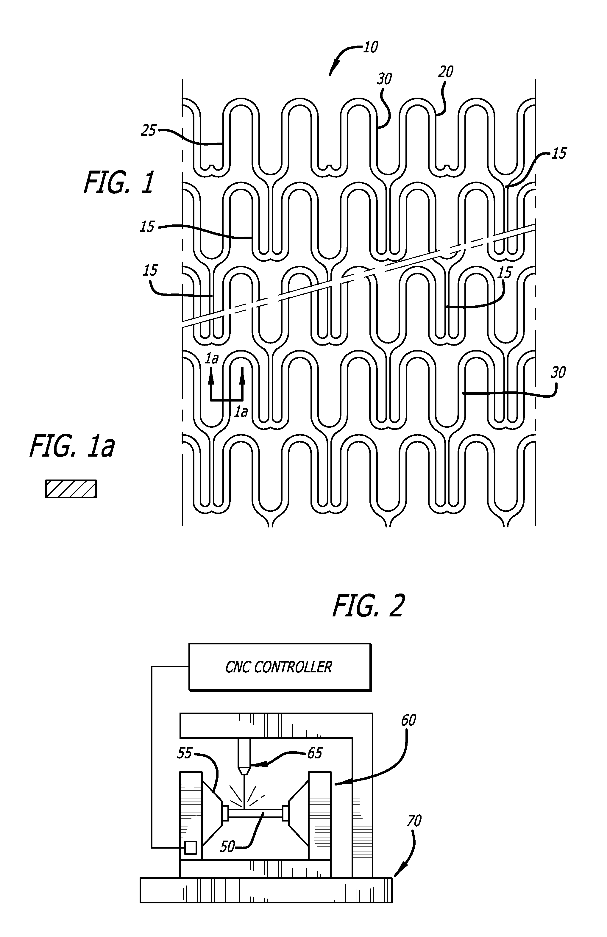
[0052]FIG. 1 is an enlarged perspective view of a stent 10 illustrating an exemplary stent pattern and showing the placement of interconnecting elements 15 between adjacent radially expandable cylindrical elements. Each pair of the interconnecting elements 15 on one side of a cylindrical element are preferably placed to achieve maximum flexibility for a stent. In the embodiment shown in FIG. 1, the stent 10 has three interconnecting elements 15 between adjacent radially expandable cylindrical elements which are 120 degrees apart. Each pair of interconnecting elements 15 on one side of a cylindrical element are offset radially 60 degrees from the pair on the other side of the cylindrical element. The alternation of the interconnecting elements results in a stent which is longitudinally flexible in essentially all directions. Various configurations for the placement of interconnecting elements are possible. However, as previously mentioned, all of the interconnecting elements of an in...


PUM

PropertyMeasurementUnit
outer diameteraaaaaaaaaa
thicknessaaaaaaaaaa

Abstract

A system and method for precision cutting using multiple laser beams is described, The system and method includes a combination of optical components that split the output of a single laser into multiple beams, with the power, polarization status and spot size of each split beam being individually controllable, while providing a circularly polarized beam at the surface of a work piece to be cut by the laser beam. A system and method for tracking manufacture of individual stents is also provided.

Description

CROSS-REFERENCES TO RELATED APPLICATIONS[0001]This application claims priority from U.S. Provisional Application No. 61 / 149,621 filed Feb. 3, 2009 and U.S. Provisional Application No. 61 / 149,645 filed Feb. 3, 2009, incorporated by reference in their entireties.[0002]This application is also related to U.S. application Ser. No. ______ entitled IMPROVED LASER CUTTING PROCESS FOR FORMING STENTS, filed Feb. 3, 2010, and U.S. application Ser. No. ______ entitled IMPROVED LASER CUTTING SYSTEM, filed Feb. 3, 2010.BACKGROUND[0003]1. Field of the Invention[0004]The present invention relates generally to implantable medical devices and to a method for manufacturing implantable medical devices. These implantable medical devices may also be capable of retaining therapeutic materials and dispensing the therapeutic materials to a desired location of a patient's body. More particularly, the present invention relates to a method for forming the structure of a stent or intravascular or intraductal m...

Claims


Application Information

Patent Timeline
Patent Type & Authority Applications(United States)
IPC IPC(8): B23K26/06B23K26/00
CPCB23K26/38A61M25/0013A61F2/90A61F2/915A61F2/91B23K26/365B23K26/361A61F2/82B23K26/0604B23K26/0626B23K26/067B23K26/36B23K26/324B23K26/362B23K26/064
Inventor CHEN, LIVON OEPEN, RANDOLF
Owner ABBOTT CARDIOVASCULAR
Why Eureka
Try Eureka