Optical pulse source device

Inactive Publication Date: 2010-08-05
OLYMPUS CORP
View PDF7 Cites 6 Cited by
  • Summary
  • Abstract
  • Description
  • Claims
  • Application Information

AI Technical Summary

Benefits of technology

[0024]According to the invention, a saturable absorber device removes noise floor included in an optical pulse train emitted from a light pulse

Problems solved by technology

However, the solid laser represented by a Titanium-sapphire laser has problems that the device is large; the stability of laser output is low; its optical system is required to be adjusted each time and thus the operability is low; the device is expensive, and the like.
Thus, the light source with a solid laser is used exclusively in a laboratory where air conditioning and a large vibration i

Method used


Image

  • Optical pulse source device
  • Optical pulse source device
  • Optical pulse source device

Examples


first embodiment

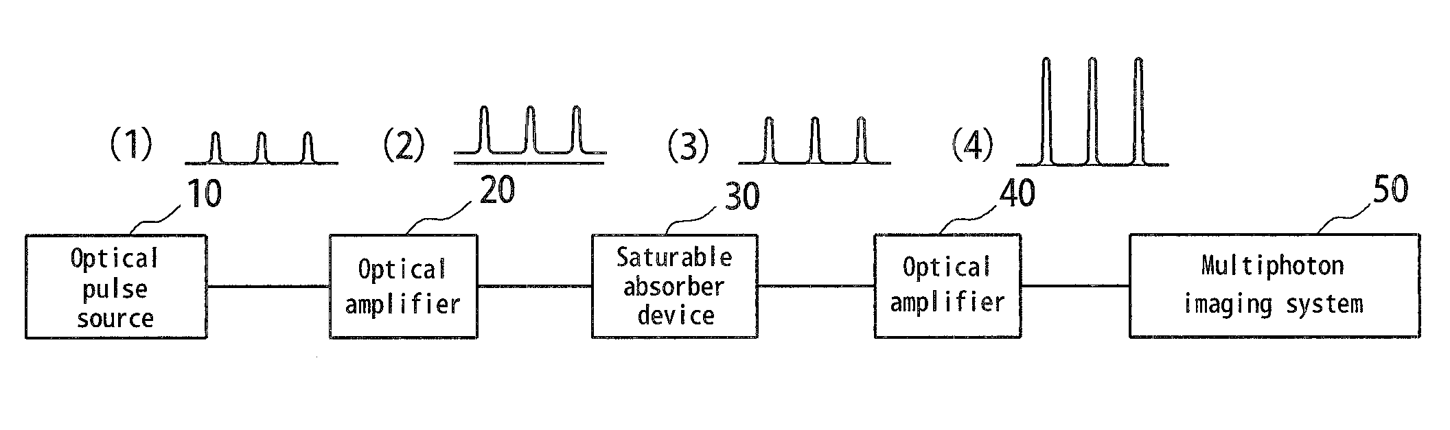
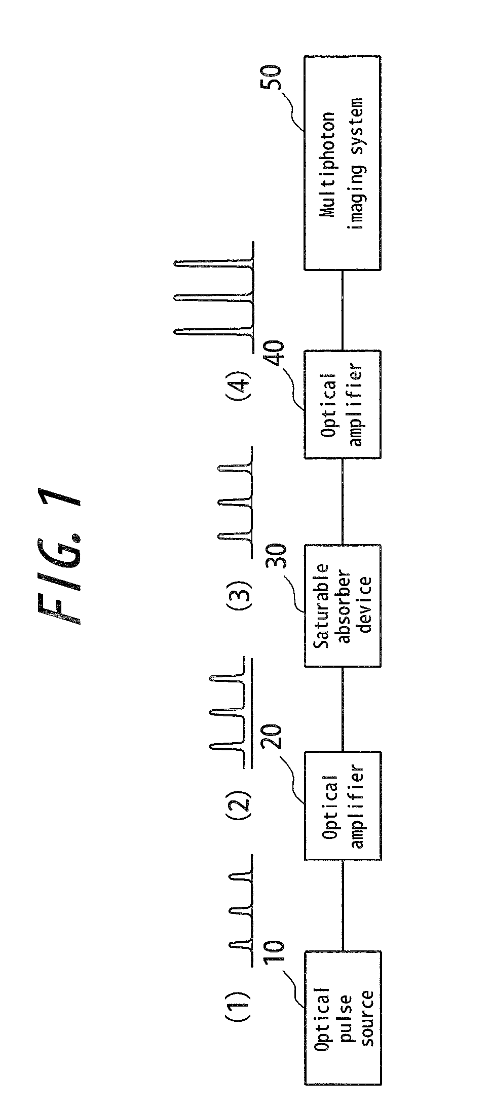
[0066]FIG. 1 is a block diagram illustrating a schematic configuration of a multiphoton imaging system having an optical pulse source device according to a first embodiment of the invention. In this figure, waveforms (1) to (4) of an optical pulse train transmitted between each component are also represented. The multiphoton imaging system according to the embodiment has an optical pulse source 10 constituting an optical pulse source device, a first optical amplifier 20, a saturable absorber device 30, a second optical amplifier 40 and a multiphoton imaging system 50. In the embodiment, the first optical amplifier 20 and the second optical amplifier 40 constitute an optical amplifying means. It is noted that the above components are connected to each other by a single-mode optical fiber.

[0067]In the above configuration, the optical pulse source 10 emits an optical pulse (1) having a repetition rate of 10 MHz and a pulse width of about 20 ps, for example, and renders the optical puls...

second embodiment

[0079]FIG. 4 is a block diagram illustrating a schematic configuration of a multiphoton imaging system having an optical pulse source device according to a second embodiment of the invention. Like FIG. 1, waveforms (1) to (4) of an optical pulse train transmitted between each component are also represented. In FIG. 4, the saturable absorber device 30 is provided not before but after the second optical amplifier 40 in the first embodiment shown in FIG. 1. That is, in this embodiment, the saturable absorber device 30 is provided after the second optical amplifying means 40.

[0080]In the multiphoton imaging system having this configuration, an optical pulse (1) emitted from the optical pulse source 10 is amplified by the first optical amplifier 20 as shown in an optical pulse (2). The amplified optical pulse (2) is further amplified by the second amplifier 40 without removing noise although its SNR is deteriorated due to ASE and the like. An optical pulse (3) output from the second ampl...

third embodiment

[0084]FIG. 6 is a block diagram illustrating a schematic configuration of a multiphoton imaging system having an optical pulse source device according to a third embodiment of the invention. Like FIG. 1 and FIG. 4, waveforms (1) to (5) of an optical pulse train transmitted between each component are also represented. In FIG. 6, a pulse compressor 70 is provided between the optical amplifier 40 and the saturable absorber device 30 in the second embodiment shown in FIG. 4. That is, in this embodiment, the saturable absorber device 30 is provided after the optical pulse compressing means.

[0085]In the multiphoton imaging system having this configuration, an optical pulse (1) emitted from the optical pulse source 10 is amplified by the first optical amplifier 20 as shown in an optical pulse (2), and is further amplified by the second optical amplifier 40 as shown in an optical pulse (3). With respect to the amplified optical pulse (3), the temporal width is compressed by the pulse compre...


PUM


Abstract

An optical pulse source device comprising an optical pulse source (10) emitting an optical pulse train, optical amplifying means (20, 40) amplifying the optical pulse train and a saturable absorber device (30) removing noise floor in the optical pulse train. There is provided an optical pulse source device for multiphoton imaging system being of small size and high stability and capable of improving the SNR by its relatively simple configuration without using a synchronous circuit or an active time gate.

Description

CROSS REFERENCE TO RELATED APPLICATION[0001]This application claims priority to and the benefit of Japan Patent Application No. 2008-76197 filed on Mar. 24, 2008, the entire content of which is incorporated herein by reference.TECHNICAL FIELD[0002]This invention relates to an optical pulse source device used in a multiphoton imaging system observing an object through a multiphoton excitation process.BACKGROUND ART[0003]It is expected that an ultrashort optical pulse source is applied in a broad range of fields including biology, medical care and hyperfine processing. Particularly in applications to biology and medical care, there is presently commercialized as the ultrashort optical pulse source a light source with a solid laser represented by a Titanium-sapphire laser. Such a light source with a solid laser is mainly used for research as a light source for nonlinear microscope imaging including a multiphoton-excited fluorescence microscope.[0004]However, the solid laser represented...

Claims


Application Information

Patent Timeline
IPC IPC(8): H01S3/13
CPCH01S3/06758H01S3/10023H01S3/1003H01S2301/02H01S5/183H01S5/4006H01S3/1618
Inventor TAIRA, KENJIYAJIMA, HIROYOSHI
Owner OLYMPUS CORP
Why Eureka
Try Eureka