Solar battery, method for manufacturing solar battery, method for manufacturing solar cell module, and solar cell module

Active Publication Date: 2010-08-12
SHARP KK
View PDF13 Cites 78 Cited by
  • Summary
  • Abstract
  • Description
  • Claims
  • Application Information

AI Technical Summary

Benefits of technology

[0031]According to the present invention, there can be provided an inexpensive solar battery in which electrodes of a solar cell and wires of a wiring substrate are electrically connected to each other at a low t

Problems solved by technology

However, as silicon substrates are getting thinner, solar cells are getting thinner, which disadvantageously results in cracks in cells caused upon operations for wiring the solar cells during fabrication of solar cell modules.
First, in the case where electrodes of a solar cell and wires of a wiring substrate are connected to each other via a solder, when a general lead-free solder (Sn—Ag—Cu-based solder or the like) is used, the solder needs to be heated to around 250° C. Where the solder needs to be heated to such a high temperature to connect the electrodes of the solar cell and the wires of the wiring substrate to each other, stress is generated due to a difference in thermal expansion coefficient between the silicon substrate of the solar cell and the wire material of the wiring substrate during cooling after the high temperature heating, which resul

Method used


Image

  • Solar battery, method for manufacturing solar battery, method for manufacturing solar cell module, and solar cell module
  • Solar battery, method for manufacturing solar battery, method for manufacturing solar cell module, and solar cell module
  • Solar battery, method for manufacturing solar battery, method for manufacturing solar cell module, and solar cell module

Examples


Example

Example 1

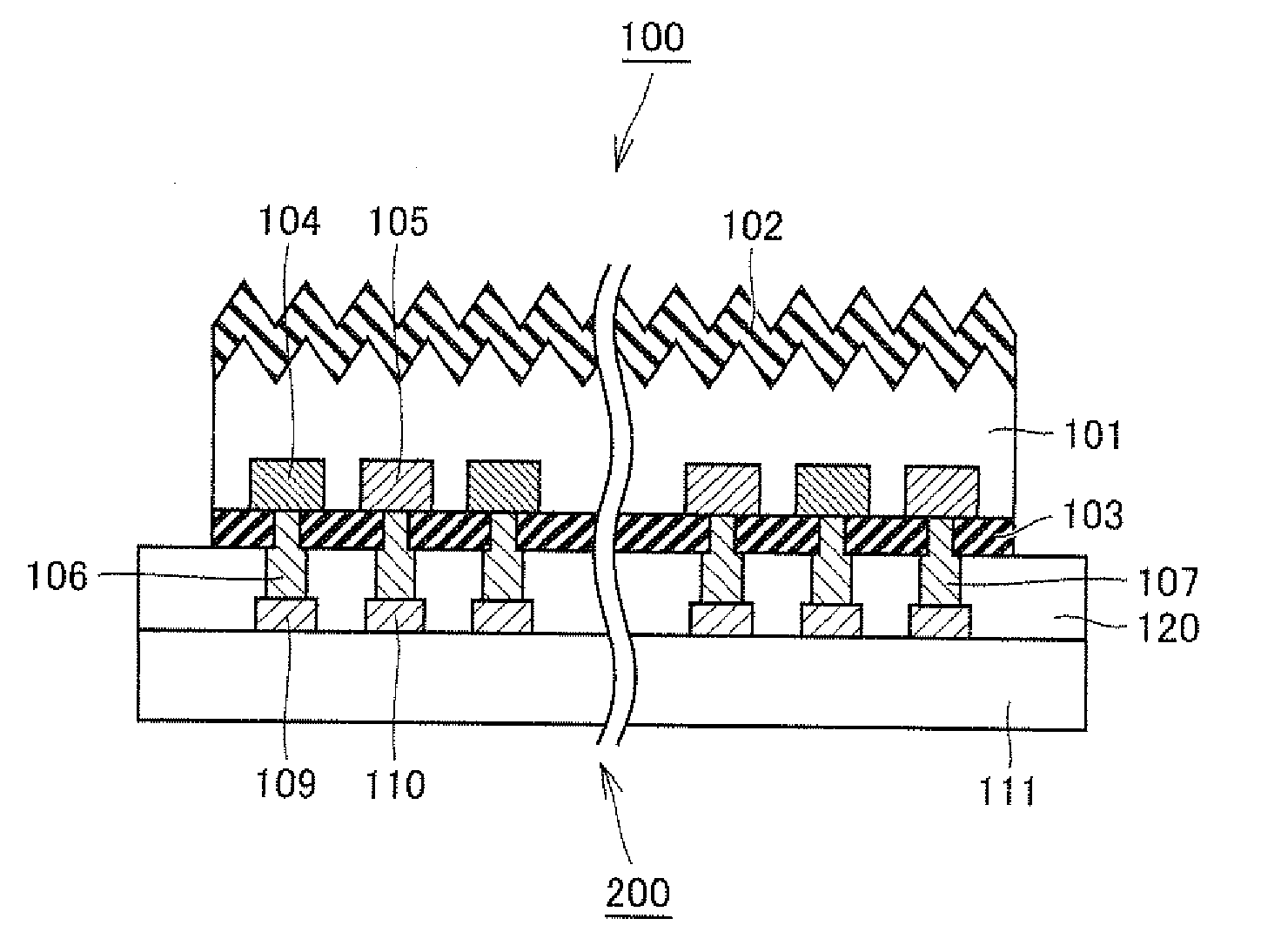
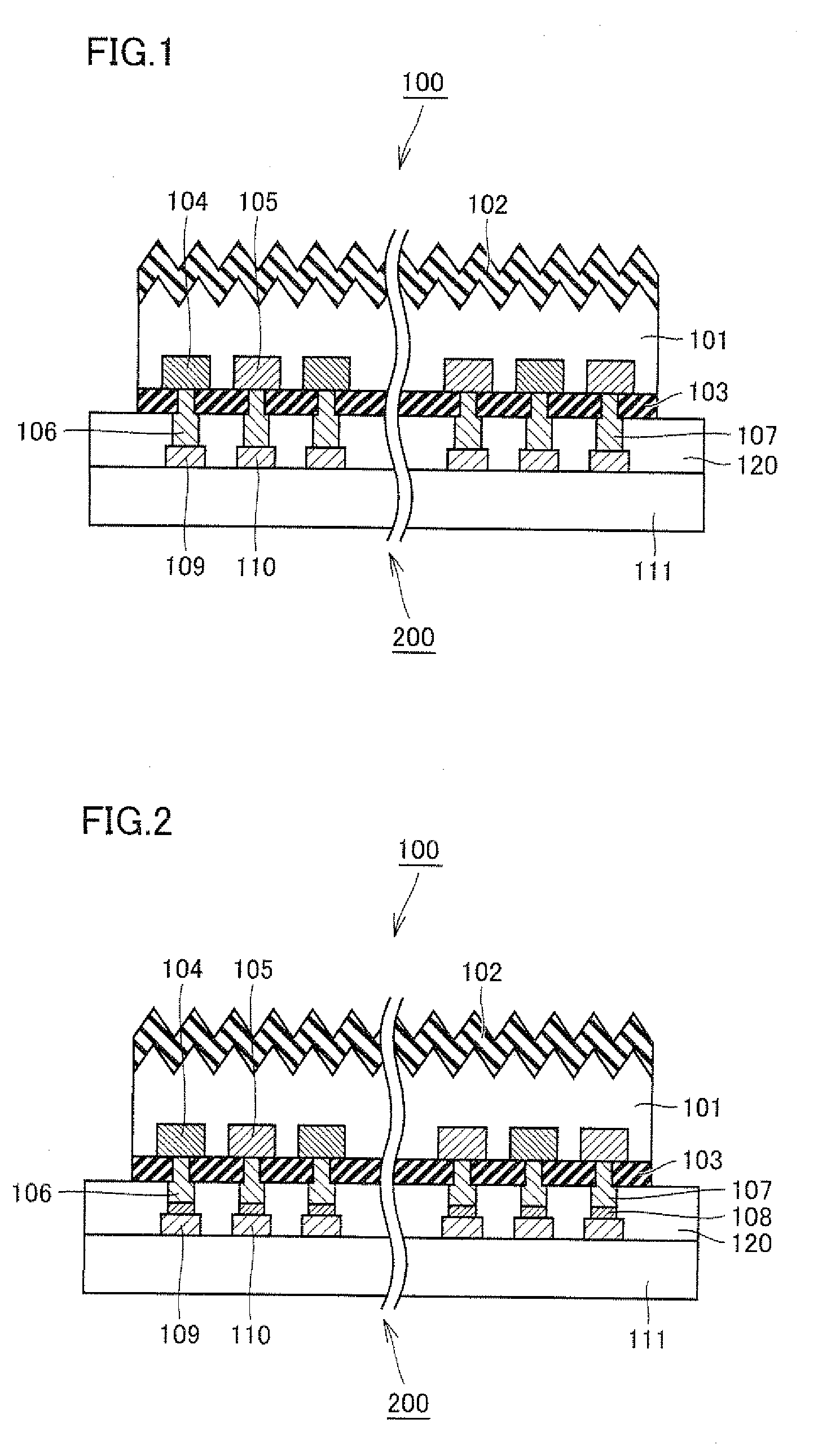
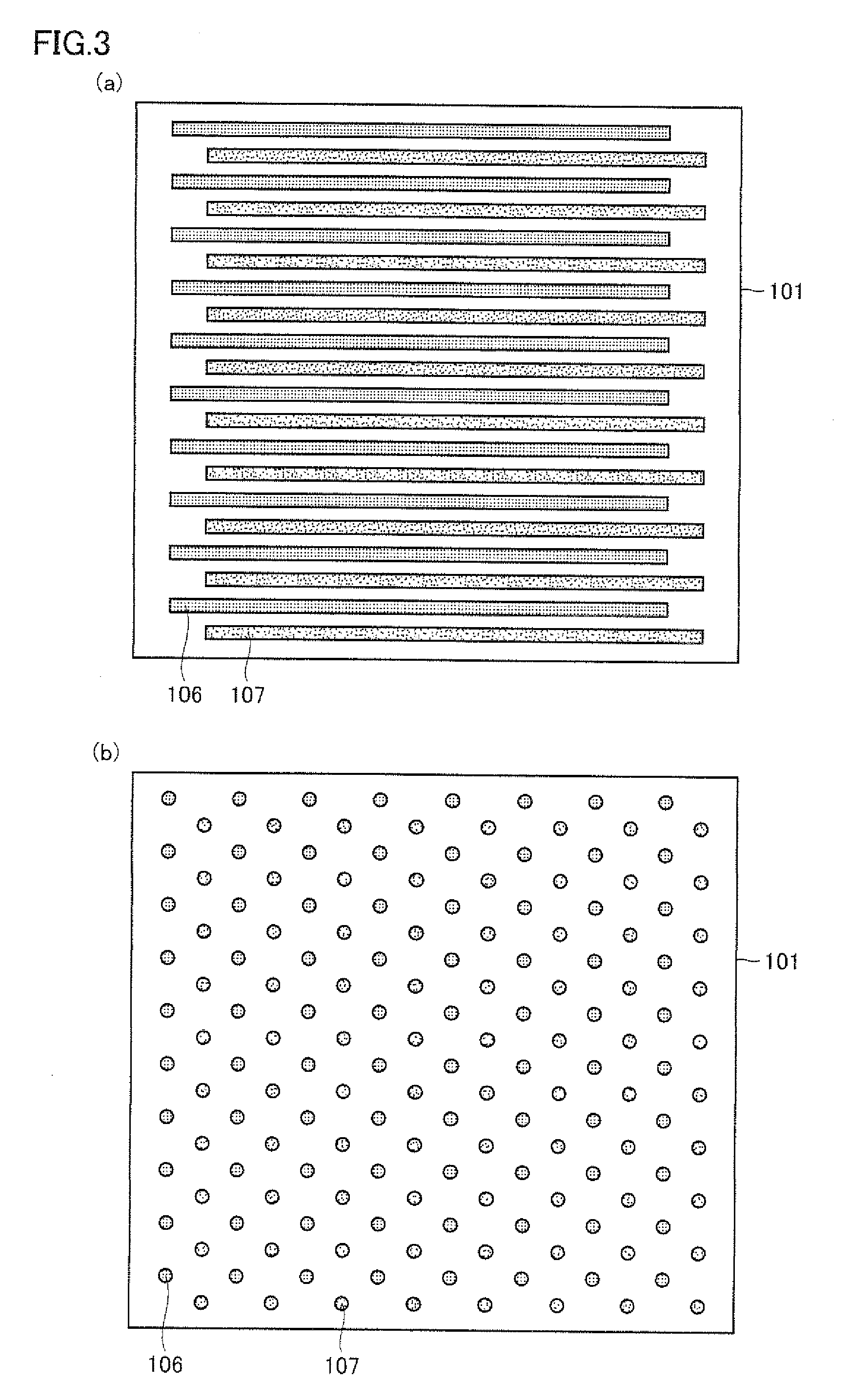
[0098]First, back-side electrode type solar cells each having a rear surface formed as shown in FIG. 3(a) were fabricated using a conventionally known method. Each solar-cell 100 was configured so that strip-shaped n electrodes 106 and p electrodes 107 were arranged alternately one by one on the rear surface of n type silicon substrate 101 having a light-receiving surface and a rear surface both having a shape of square with each side of 100 mm.

[0099]Then, the method shown in FIG. 5(a)-FIG. 5(c) was employed to transfer wires made of copper to an adhesive agent 120 provided on an insulative substrate 111 made of PET. In this way, a wiring substrate 200 was fabricated. As adhesive agent 120, an acrylic-based viscous adhesive agent was used.

[0100]Then, as shown in FIG. 7, sixteen solar cells 100 were placed on one wiring substrate 200. In this way, a solar battery was fabricated in which solar cells 100 were fixed onto wiring substrate 200 by adhesive agent 120. In fabricatin...

Example

Example 2

[0106]First, back-side electrode type solar cells each having a rear surface formed as shown in FIG. 3(a) were fabricated using a conventionally known method. Each solar cell 100 was configured so that strip-shaped n electrodes 106 and p electrodes 107 were arranged alternately one by one on the rear surface of n type silicon substrate 101 having a light-receiving surface and a rear surface both having a shape of square with each side of 100 mm, Each of the solar cells was soaked in an Sn—Bi solder bath to coat the electrode portions with the solder.

[0107]Then, as shown in FIG. 8(a), an acrylic-based viscous adhesive agent was applied to a portion of the rear surface of the solar cell other than the electrodes provided thereon, by means of screen printing. Thereafter, it was baked at 100° C., thus exhibiting viscosity of the viscous adhesive agent.

[0108]Then, as shown in FIG. 7, sixteen solar cells 100 were placed on one wiring substrate 200. In this way, a solar battery wa...


PUM

PropertyMeasurementUnit
Temperatureaaaaaaaaaa
Viscosityaaaaaaaaaa

Abstract

The present invention provides a solar battery including a solar cell; a wiring substrate having a wire to be electrically connected to an electrode provided in the solar cell; and an adhesive agent for adhering the solar cell and the wiring substrate to each other. The present invention also provides a method for manufacturing the solar battery, a method for manufacturing a solar cell module using the solar battery, and the solar cell module.

Description

TECHNICAL FIELD[0001]The present invention relates to a solar battery, a method for manufacturing a solar battery, a method for manufacturing a solar cell module, and a solar cell module, in particular, a solar battery in which electrodes of a solar cell and wires of a wiring substrate can be electrically connected to each other at a low temperature readily to attain highly reliable connection therebetween and relatively good electric characteristics; a method for manufacturing the solar battery; a method for manufacturing a solar cell module using the solar battery; and the solar cell module.BACKGROUND ART[0002]In recent years, problems of exhaustion of energy resources and global environmental issues such as increasing CO2 in the atmosphere have driven demands for development of clean energy. In particular, utilization of solar batteries for photovoltaic power generation has been developed, been put into practical use, and been expanded as a new energy source.[0003]An exemplary ma...

Claims


Application Information

Patent Timeline
IPC IPC(8): H01L31/00B32B38/10B29C65/48
CPCH01L31/048H01L31/0516Y10T156/10H01L31/049Y02E10/50H01L31/0201
Inventor FUNAKOSHI, YASUSHI
Owner SHARP KK
Why Eureka
Try Eureka