Plasma processing apparatus, and maintenance method and assembling method of the same

a technology of plasma processing apparatus and maintenance method, which is applied in the direction of charge manipulation, instruments, furniture, etc., can solve the problems of deteriorating the production yield of processing wafers, increasing the amount of adsorption, and the inside of the apparatus being exposed to the atmosphere, so as to shorten the exhaust time

Active Publication Date: 2010-08-12
TOKYO ELECTRON LTD
View PDF12 Cites 12 Cited by
  • Summary
  • Abstract
  • Description
  • Claims
  • Application Information

AI Technical Summary

Benefits of technology

[0017]In terms of the above problems, the present invention provides a plasma processing apparatus that may shorten exhaust time.

Problems solved by technology

The detached deposit becomes a contaminant that may deteriorate the production yield in processing a wafer.
However, at that moment, the inside of the apparatus is exposed to the atmosphere.
In the prior art, however, the entirety of the inside of the apparatus is exposed to the atmosphere during maintenance work so that the exhaust chamber EC which is not necessarily opened during maintenance as well as the processing chamber PC that performs maintenance is exposed to the atmosphere.
Over time after initiation of exposure to the atmosphere, the moisture adsorbing amount increases and it requires a long time for the moisture adsorbing amount through the film surface to be saturated and converged.
As a consequence, the alumite included in the exhaust chamber EC, which is not necessary for exposure to the atmosphere, absorbs a considerable amount of moisture in the atmosphere, and thus it requires a long exhaust time to obtain a good vacuum exhaust property inside the processing vessel after maintenance.
From above, eight or more hours of exhaust time was required to satisfy both conditions, and this was one of primary causes of deteriorating productivity of the apparatus.
Accordingly, there is no means to actively control the temperature inside the exhaust chamber EC to suppress moisture in the atmosphere from being introduced into the chamber EC.
Further, there is no means to accelerate gas release during vacuum exhaust, either.

Method used


Image

  • Plasma processing apparatus, and maintenance method and assembling method of the same
  • Plasma processing apparatus, and maintenance method and assembling method of the same
  • Plasma processing apparatus, and maintenance method and assembling method of the same

Examples


first embodiment

[0037](Construction of Overall Apparatus)

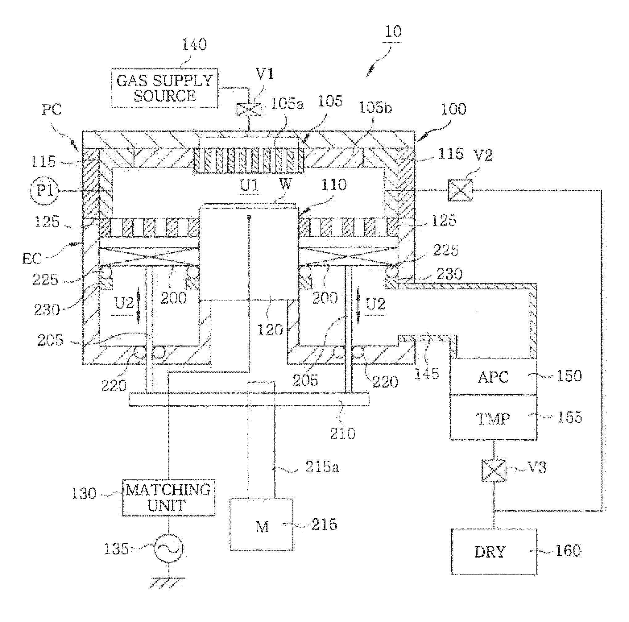
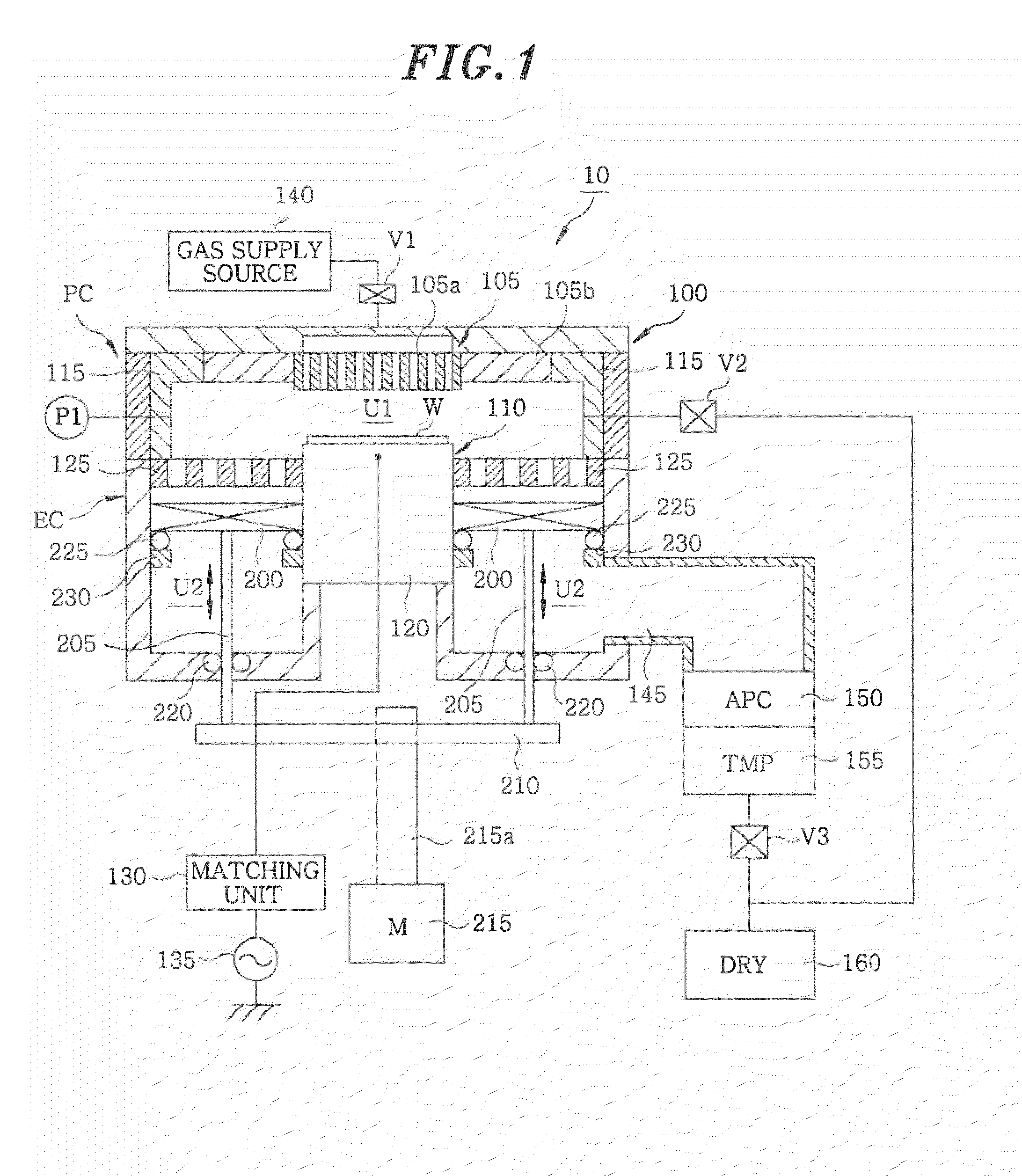
[0038]First of all, a construction of an overall plasma processing apparatus with electrodes according to an embodiment of the present invention will be described with reference to FIG. 1. FIG. 1 is a longitudinal cross section view schematically illustrating an etching processing apparatus (parallel plate type plasma processing apparatus) according to an embodiment of the present invention. The etching processing apparatus 10 is an example of a plasma processing apparatus that generates plasma using electromagnetic wave energy to perform plasma processing on a wafer W.

[0039]The etching processing apparatus 10 includes a processing vessel 100 that performs plasma processing on the wafer W. The processing vessel 100 is cylindrical and includes an upper electrode 105 and a lower electrode 110 that faces the upper electrode 105. The upper electrode 105 includes a gas shower header 105a and a quartz shield 105b that is surrounded by a deposit shi...

second embodiment

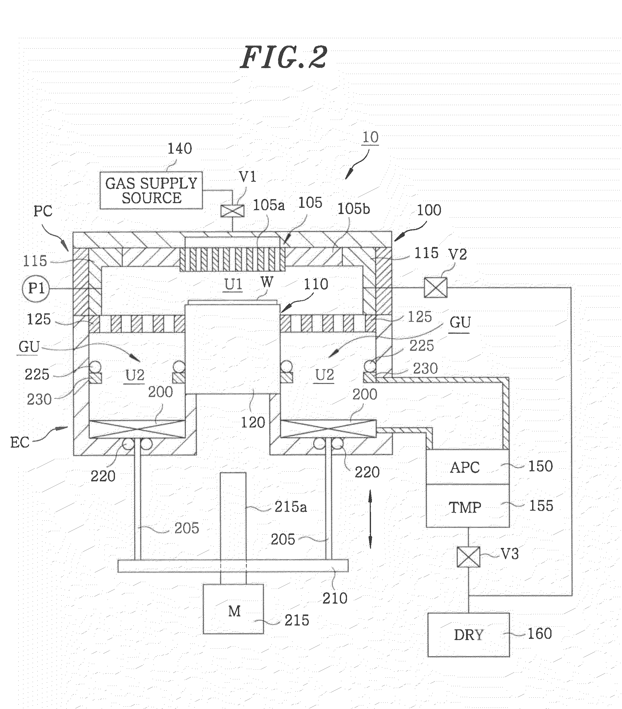
[0062]An etching processing apparatus 10 according to a second embodiment of the present invention will now be described with reference to FIG. 6. The etching processing apparatus 10 according to the second embodiment is different from the etching processing apparatus according to the first embodiment in location of the cover. Hereinafter, the descriptions will focus on the difference, and descriptions on parts identical to the first embodiment will be omitted.

[0063](Operation of Seal-Off Cover)

[0064]In the etching processing apparatus 10 according to the embodiment, as shown in FIG. 6, a gas seal-off cover 250 is arranged under the seal gate ring 230 and below the baffle plate 125. The gas seal-off cover 250 is an example of a blocking cover that blocks communication between the inside of the processing chamber PC and the inside of the exhaust chamber EC.

[0065]The exhaust space U2 from the gas seal-off cover 250 to the APC 150 is maintained to a predetermined pressure of gas atmosp...

third embodiment

[0080]Next, an etching processing apparatus according to a third embodiment of the present invention will be described with reference to FIG. 8. The etching processing apparatus 10 according to the third embodiment differs from the etching processing apparatus 10 according to the first embodiment in that a temperature control mechanism 300 is provided at the exhaust chamber EC. Hereinafter, the descriptions will focus on the difference and repetitive descriptions on parts equal to those in the first embodiment will be omitted.

[0081](Temperature Control of Exhaust Chamber)

[0082]The etching processing apparatus 10 shown in FIG. 8 includes the temperature control mechanism 300 at an outer wall of the exhaust chamber EC in addition to the construction of the etching processing apparatus 10 shown in FIG. 1. The temperature control mechanism 300 includes a heating mechanism and a cooling mechanism. In the temperature control of the exhaust chamber EC, the temperature of the exhaust chambe...


PUM

PropertyMeasurementUnit
pressureaaaaaaaaaa
pressureaaaaaaaaaa
atmospheric pressureaaaaaaaaaa

Abstract

A plasma processing apparatus includes a processing chamber that converts a processing gas introduced from a gas supply source into plasma and performs plasma processing on a target object, an exhaust chamber that communicates with the inside of the processing chamber to exhaust a gas converted into plasma from the processing chamber, and a blocking cover that is provided in the exhaust chamber to block communication between the inside of the processing chamber and the inside of the exhaust chamber.

Description

CROSS-REFERENCE TO RELATED APPLICATIONS [0001]This application claims priority to Japanese Patent Application No. 2009-030459 filed on Feb. 12, 2009, the entire contents of which are incorporated herein by reference.FIELD OF THE INVENTION [0002]The present invention is related to a plasma processing apparatus, a maintenance method and an assembling method of a plasma processing apparatus.BACKGROUND OF THE INVENTION[0003]In a plasma processing apparatus, a target object is micro processed by plasma. For example, in a plasma etching processing apparatus shown in FIG. 9, an upper electrode 905 and a lower electrode 910 are arranged to be opposite to each other in a processing vessel 900 to generate plasma between the electrodes 905 and 910. The upper electrode 905 includes a gas shower head 905a and a quartz shield 905b, and a deposit shield 915 surrounding the quartz shield 905b. [0004]A baffle plate 925 is arranged at the periphery of a susceptor 920, which is connected to a high fre...

Claims


Application Information

Patent Timeline
Patent Type & Authority Applications(United States)
IPC IPC(8): G05D23/00C23F1/08B65G49/00B23P11/00
CPCH01J37/32522Y10T29/49826H01J37/32834
Inventor SAITO, MASASHI
Owner TOKYO ELECTRON LTD
Why Eureka
Try Eureka