Approach method for probe and sample in scanning probe microscope

a scanning probe and microscope technology, applied in the direction of instruments, nuclear engineering, material analysis using wave/particle radiation, etc., can solve the problems of reducing the resolution of the topographic image and the damage to the sample, the long time of the probe, and the reduction of measurement efficiency, so as to speed up the approach operation and improve the operability. , the effect of high resolution

Active Publication Date: 2010-08-12
HITACHI HIGH TECH SCI CORP
View PDF15 Cites 9 Cited by
  • Summary
  • Abstract
  • Description
  • Claims
  • Application Information

AI Technical Summary

Benefits of technology

[0037]By providing such a function, the probe and the sample may be allowed to approach each other easily without making complicated settings, to thereby improve operability.
[0038]According to the present invention, by allowing the probe to approach the sample by the method as described above in the oscillating mode scanning probe microscope, which oscillates the cantilever on the first- or higher-order resonance spectrum, or the contact mode scanning probe microscope, the probe may be prevented from contacting the sample to be damaged and thereby breaking the tip of the probe and the sample during the approach operation, and further, the probe and the sample may be operated at high speed by the coarse-movement mechanism and the coarse-movement mechanism may be stopped reliably in time before the probe and the sample are brought into contact with each other. Further, even after the coarse-movement mechanism is stopped, the probe and the sample may be allowed to approach each other up to the measurement area in a short time while preventing the tip of the probe and the sample from being broken.
[0039]As a result, the scanning probe microscope may perform a measurement with high resolution because the measurement is performed without damaging the probe and the sample, to thereby speed up the approach operation, reduce the time required for the measurement, and improve the operability.

Problems solved by technology

Specifically, if the probe and the sample collide with each other when the probe and the sample approach each other, the tip of the probe and the sample surface are broken, to thereby lead to reduced resolution in measuring the topographic image and the damage to the sample.
Alternatively, when the speed of the coarse-movement mechanism is lowered to allow the probe and the sample to approach each other more carefully, it takes a long time for the probe and the sample to approach each other, to thereby reduce the measurement efficiency.
Therefore, it is difficult to stop the coarse-movement mechanism before causing the collision, and it is more challenging to allow the probe and the sample to approach each other without causing the collision.
In the conventional method, when the coarse-movement mechanism is operated at high speed, the coarse-movement mechanism may be stopped so late that the probe and the sample may collide with each other.
As a result, the approach has taken a long time.
However, a special electric circuit such as the FM demodulator is required to perform the measurement using the phase difference signal as the reference signal, and processing for the approach becomes complicated.
Especially in the higher-order oscillating modes, it has often been the case that the amplitude or the phase of the cantilever hardly changes until the probe and the sample are brought close to each other up to near the measurement area, which often leads to the collision between the probe and the sample.
Further, in the case of measuring in the contact mode, the probe and the sample often collide with each other to generate a larger impact than in the oscillating mode upon the collision, and hence there has been no choice but to lower the speed of the coarse-movement mechanism.

Method used


Image

  • Approach method for probe and sample in scanning probe microscope
  • Approach method for probe and sample in scanning probe microscope
  • Approach method for probe and sample in scanning probe microscope

Examples


first embodiment

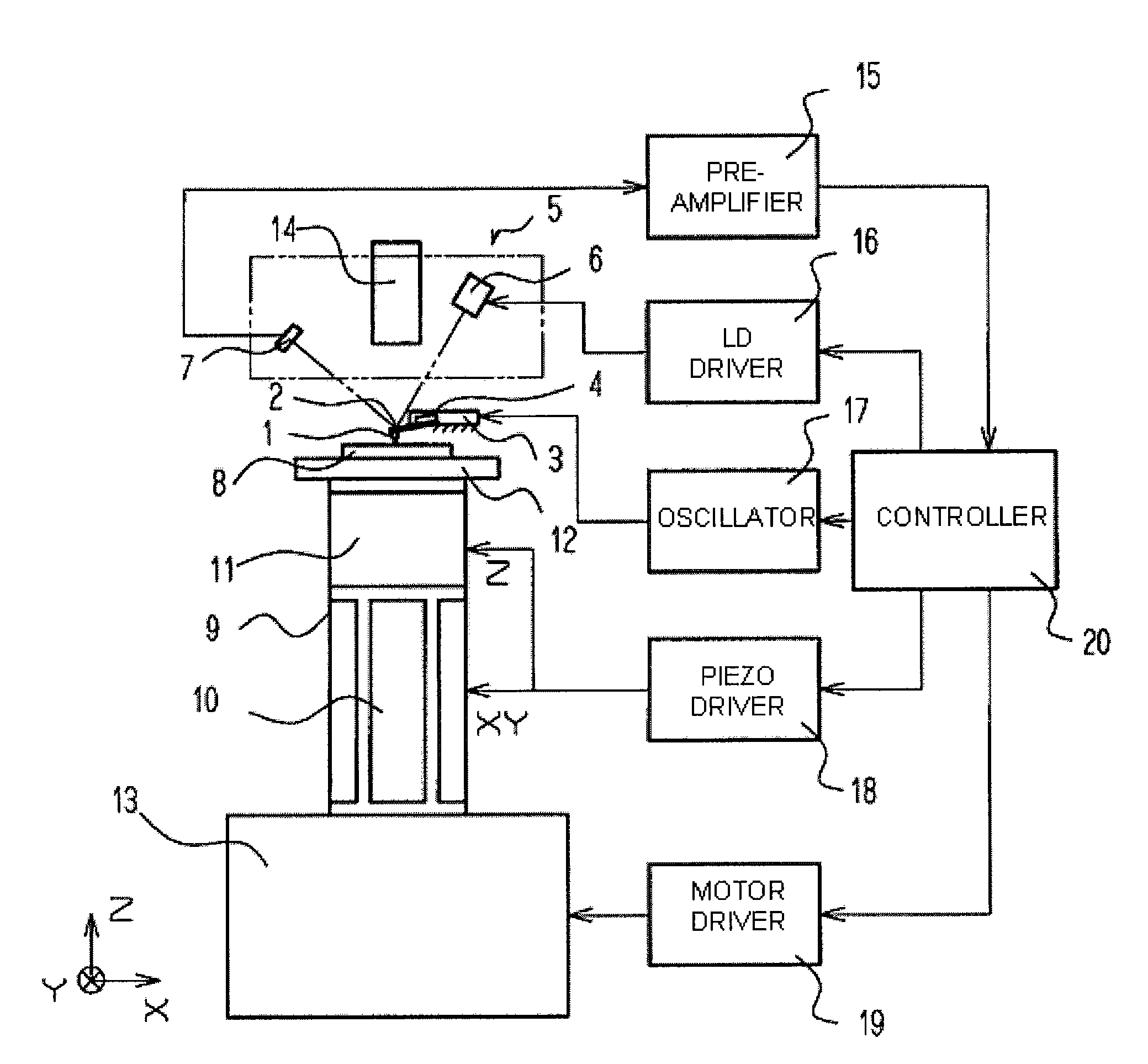
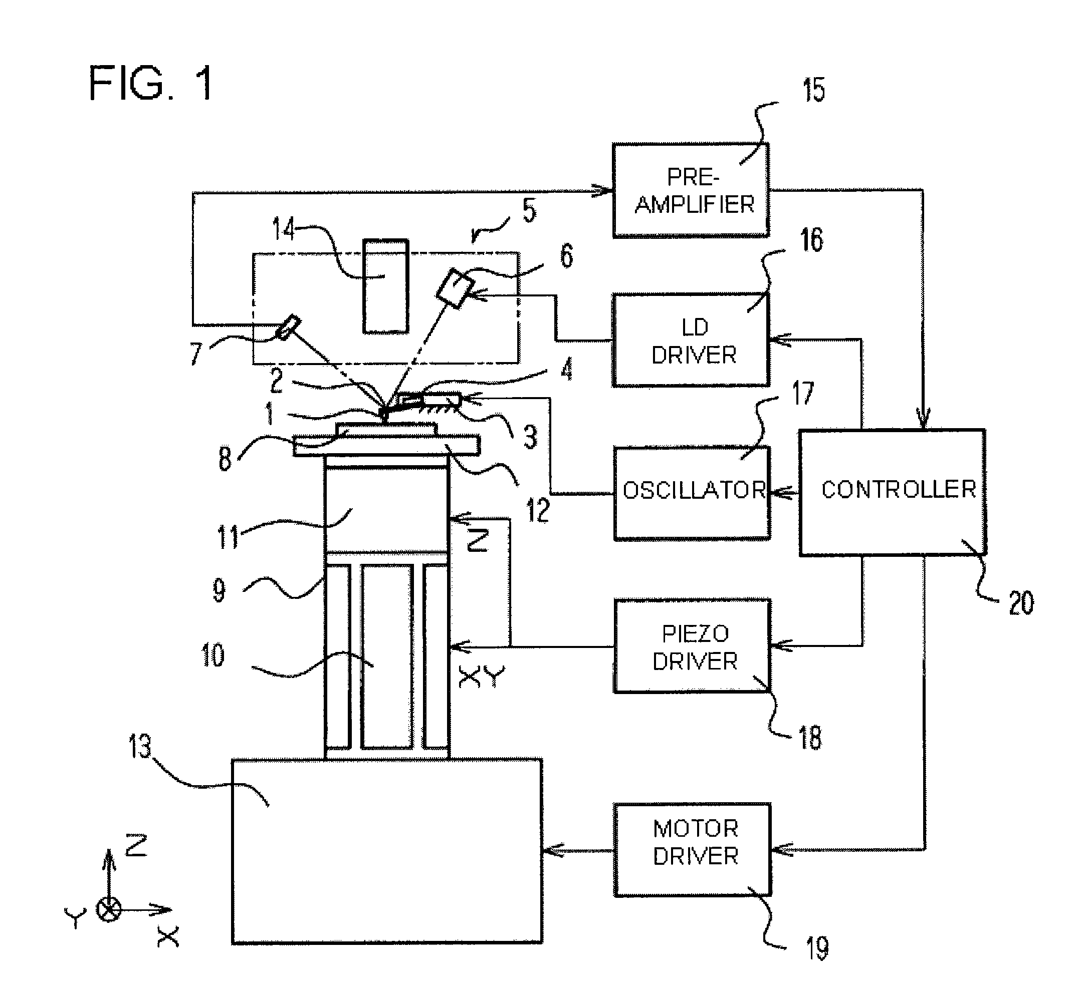
[0052]FIG. 1 is a schematic diagram illustrating a scanning probe microscope according to a first embodiment of the present invention. In this embodiment, a cantilever 2 which is made of silicon and has a probe 1 at its distal end is fixed to a cantilever holder 3. A vibrator 4 formed of a piezoelectric element for exciting the cantilever 2 is attached to the cantilever holder 3. When the scanning probe microscope is used as an oscillating mode scanning probe microscope, an alternate current (AC) voltage is applied to the piezoelectric element constituting the vibrator 4 to oscillate the vibrator 4 and hence oscillate the cantilever 2.

[0053]A displacement detecting mechanism 5 for detecting a displacement of the cantilever 2 includes a semiconductor laser 6 and a two-cell photodetector 7 to detect the deflection of the cantilever 2 in a mode generally called optical lever method. First, a beam from the semiconductor laser 6 is condensed and a back surface of the cantilever 2 is irra...

second embodiment

[0083]Described next is an operation principle of a measurement in a case where a higher-order resonant mode of the cantilever is used for the measurement according to a second embodiment of the present invention. In this embodiment, the same apparatus as in the first embodiment of FIG. 1 is used for the measurement. At this time, the oscillation of the cantilever 2 in the measurement is generated as torsional oscillation around the long axis of the cantilever 2.

[0084]The apparatus of FIG. 1 causes the oscillator 17 to generate an arbitrary AC signal of a higher-order resonance spectrum for generating the torsional oscillation of the cantilever 2, and applies the AC signal to the vibrator 4 to oscillate the cantilever 2. In the torsional oscillation, the tip of the probe 1 oscillates substantially parallel to the surface of the sample 8, and the variation in amplitude with respect to the distance between the probe 1 and the sample 8 is smaller than the deflection mode of the cantile...

third embodiment

[0087]Described next is an operation principle of a measurement in a contact mode according to a third embodiment of the present invention.

[0088]Apparatus components of this embodiment are the same as those of the first embodiment, and the apparatus of FIG. 1 is used.

[0089]When a measurement is performed in the contact mode, it is more difficult to stop the probe 1 and the sample 8 with an appropriate distance therebetween than in the oscillating mode. For example, when the sample 8 and the probe 1 are electrically charged, the cantilever 2 is deflected by an electrostatic force and the approach operation is stopped at a long distance to increase the time required to bring the sample 8 and the probe 1 close to each other up to a measurable area. Further, when the stop condition that may bring the probe 1 and the sample 8 close to each other up to the measurable area is set, it is often the case that the probe 1 and the sample 8 collide with each other. As for an impact upon the coll...


PUM


Abstract

In detecting a displacement of a cantilever (2) by a displacement detecting mechanism (5) and allowing a probe (1) and a sample (8) to approach each other by at least one of a coarse-movement mechanism (13) and a vertical direction fine-movement mechanism (11) at the same time, an excitation mechanism (4) excites the cantilever (2) with a first excitation condition and the probe (1) and the sample (8) are allowed to approach each other with a first stop condition, and then the cantilever (2) is excited with a second excitation condition different from the first excitation condition, a second stop condition is set, and the probe (1) and the sample (8) are allowed to approach each other by the at least one of the vertical direction fine-movement mechanism (11) and the coarse-movement mechanism (13) until the second stop condition is satisfied.

Description

RELATED APPLICATIONS[0001]This application claims priority under 35 U.S.C. §119 to Japanese Patent Application Nos. 2009-028747 filed on Feb. 10, 2009 and 2009-267578 filed on Nov. 25, 2009, the entire content of which is hereby incorporated by reference.BACKGROUND OF THE INVENTION[0002]1. Technical Field[0003]The present invention relates to an approach method for a probe and a sample in a scanning probe microscope for relatively scanning the probe and the sample to measure a shape and a physical property of a surface of the sample, process the surface of the sample, or move a substance on the surface of the sample by the probe while controlling a distance by detecting an interaction between a cantilever including the probe at its distal end and the surface of the sample in the atmosphere, a vacuum, or a solution.[0004]2. Description of the Related Art[0005]Referring to FIGS. 5 and 6, a configuration of a conventional scanning probe microscope is described (see JP 2007-33321 A).[00...

Claims


Application Information

Patent Timeline
Patent Type & Authority Applications(United States)
IPC IPC(8): G01Q10/00
CPCG01Q10/06B82Y35/00
Inventor IYOKI, MASATOSHIKAKURA, YOSHITERUWATANABE, MASAFUMI
Owner HITACHI HIGH TECH SCI CORP
Why Eureka
Try Eureka