
Method for fabricating silicon NANO wire, solar cell including silicon NANO wire and method for fabricating solar cell

a solar cell and solar cell technology, applied in the field of solar cell manufacturing methods, can solve the problems that the technology of fabricating miniaturized, thin film solar cells by a low-temperature process is unlikely to be achieved

Inactive Publication Date: 2010-08-19
KOREA INST OF IND TECH
View PDF9 Cites 33 Cited by
  • Summary
  • Abstract
  • Description
  • Claims
  • Application Information

AI Technical Summary

Benefits of technology

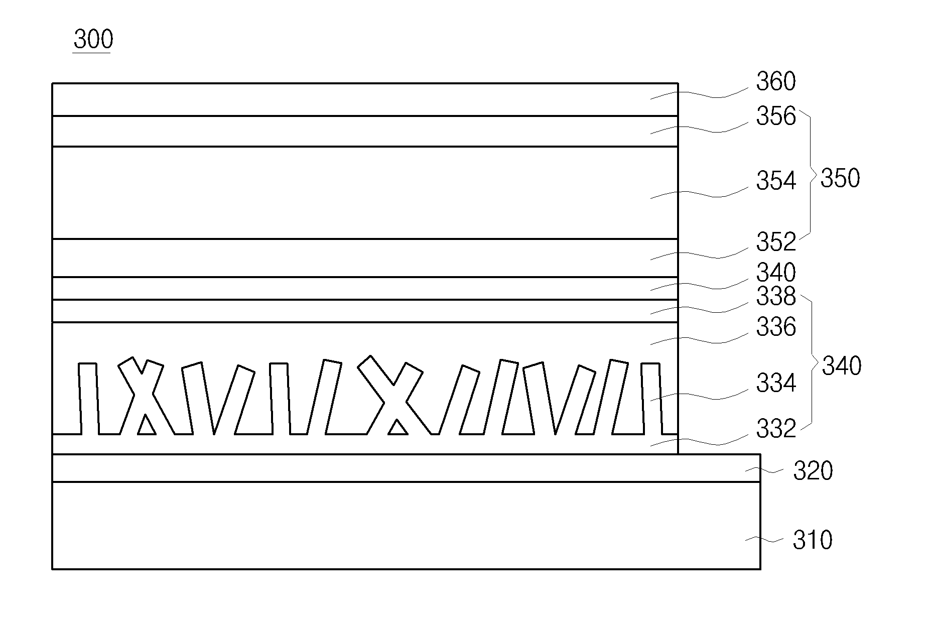
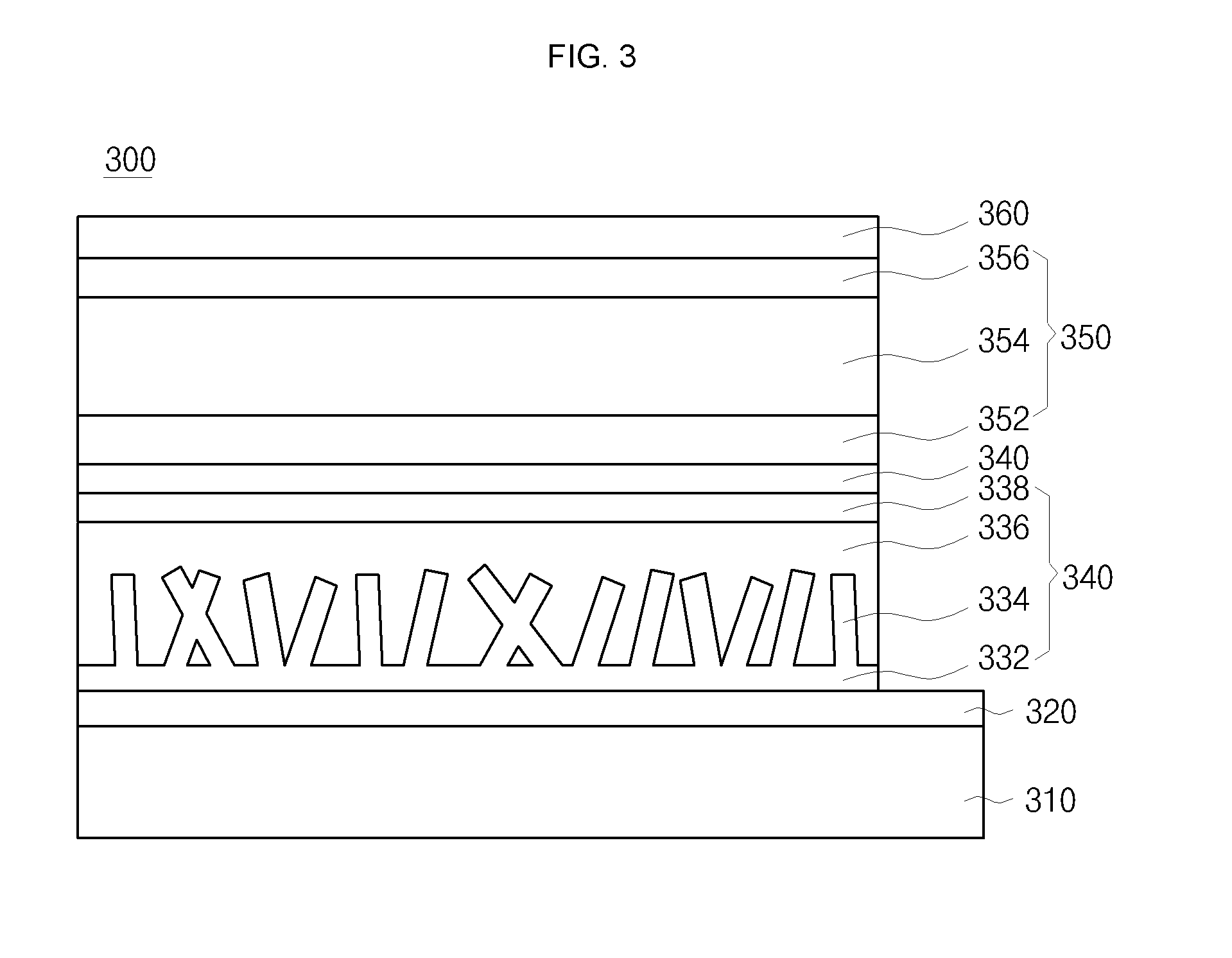
The present invention provides a method for fabricating a silicon nano wire using a low-temperature plasma process. This method can be used to fabricate a solar cell using the silicon nano wire as a part of the cell. The method includes forming a seed layer on a substrate, growing silicon nano wires on the seed layer, and using a transparent conductive oxide layer and antireflective layer to improve the efficiency of the solar cell. The silicon nano wire has a length of about 2 to 5 μm and a diameter of about 1 to 5 nm. The method can be performed using a sputtering or evaporation method to form the metal film layer and the first-type Si nano wires. The metal film layer can be formed from metal nano particles using inductively coupled plasma chemical vapor deposition or very high frequency-chemical vapor deposition. The method can be used to fabricate a solar cell with high efficiency.

Problems solved by technology

Thus, due to the complexity of a high-temperature process as well as the supply shortage of Si material, technology of fabricating miniaturized, thin film solar cells by a low-temperature process is unlikely achievable.

Method used


Image

  • Method for fabricating silicon NANO wire, solar cell including silicon NANO wire and method for fabricating solar cell
  • Method for fabricating silicon NANO wire, solar cell including silicon NANO wire and method for fabricating solar cell
  • Method for fabricating silicon NANO wire, solar cell including silicon NANO wire and method for fabricating solar cell

Examples


Embodiment Construction

[0051]Hereinafter, embodiments of the present invention will be described in detail with reference to the accompanying drawings.

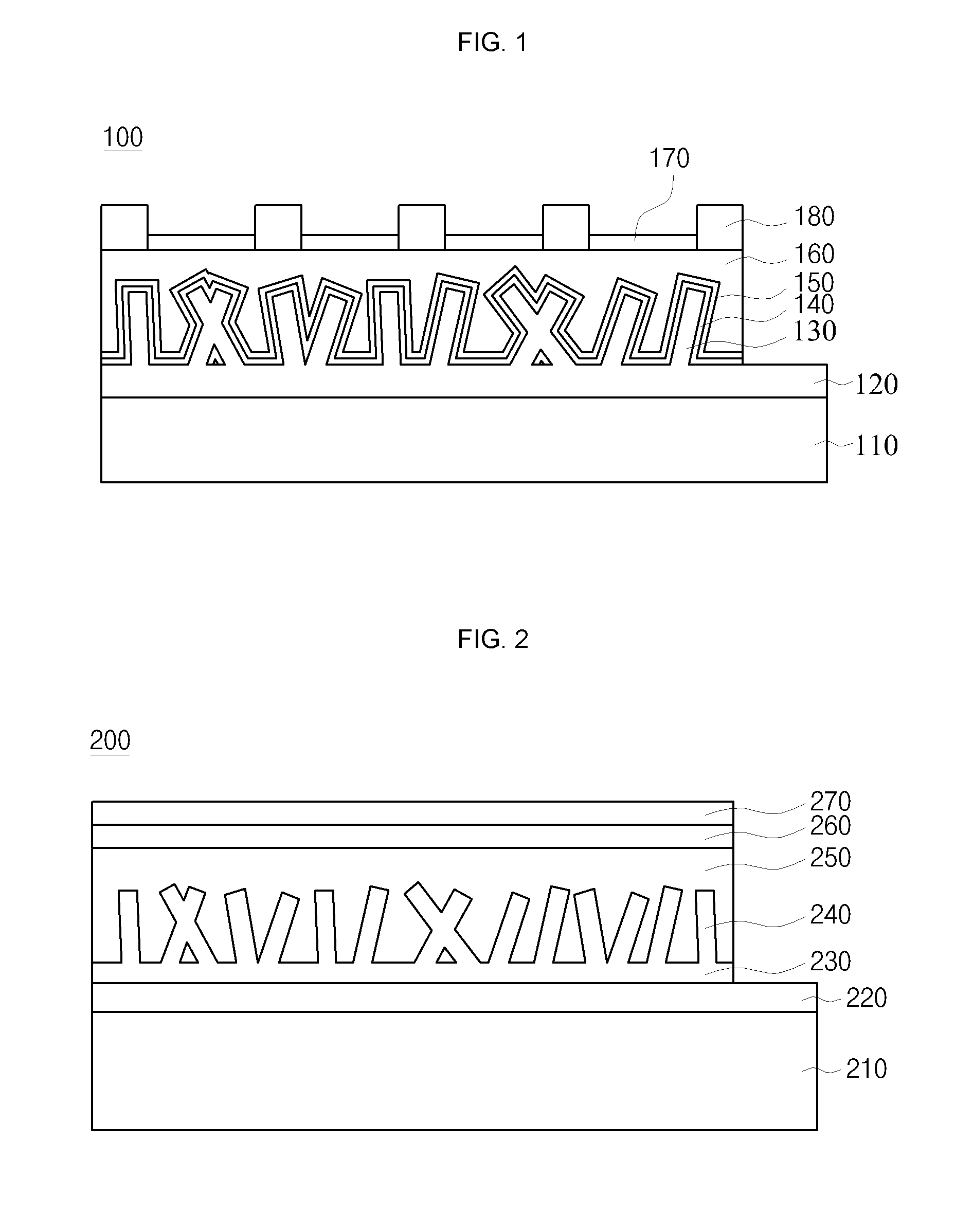
[0052]FIG. 1 is a sectional view illustrating a solar cell according to an embodiment of the present invention.

[0053]Referring to FIG. 1, the solar cell 100 according to an embodiment of the present invention includes a substrate 210, a first++-type poly-Si layer 120, a first-type silicon nano wire layer 240, an intrinsic layer 250, a second-type doping layer 150, a TCO (Transparent Conducting Oxide) layer 160, an antireflective layer 170, and a front electrode 180.

[0054]Here, the first type is a P type, and the second type is an N type. On the other hand, the first type may be an N type, and the second type is a P type.

[0055]Meanwhile, the first-type or second-type labeling with marks “++” signifies impurity doping level. The first or second type with a “+” mark means a type doped with higher impurity level than that without “+” mark. Similarly, the first ...


PUM

PropertyMeasurementUnit
diameteraaaaaaaaaa
diameteraaaaaaaaaa
thicknessaaaaaaaaaa

Abstract

A method for fabricating a silicon nano wire, a solar cell including the silicon nano wire and a method for fabricating the solar cell. The solar cell includes a substrate, a first++-type poly-Si layer formed on the substrate, a first-type silicon nano wire layer including a first-type silicon nano wire grown from the first++-type poly-Si layer, an intrinsic layer formed on the substrate having the first-type silicon nano wire layer, and a second-type doping layer formed on the intrinsic layer.

Description

CROSS-REFERENCE TO RELATED APPLICATION[0001]This application claims priority to and the benefit of Korean Patent Application Nos. 10-2009-0013458, filed on Feb. 18, 2009, 10-2009-0013465, filed on Feb. 18, 2009, and 10-2009-0101154, filed on Oct. 23, 2009, the entire content of which is incorporated herein by reference.BACKGROUND OF THE INVENTION[0002]1. Field of the Invention[0003]The present invention relates to a method for fabricating a silicon nano wire, a solar cell including the silicon nano wire and a method for fabricating the solar cell.[0004]2. Related Art[0005]As obligations to reduce greenhouse gas emission are currently accelerating under the Climate Change Convention, carbon dioxide market is booming. Accordingly, new renewable energy fields are drawing greater attention. A solar cell, a representative example of the new recyclable energy fields, directly converts sunlight, which is a limitless source of clean energy, into electricity using the photoelectric effect.[0...

Claims


Application Information

Patent Timeline
Patent Type & Authority Applications(United States)
IPC IPC(8): H01L31/00H01L21/20H01L31/18H01L31/076H01L31/077
CPCB82Y20/00H01L31/035236H01L31/03529Y02E10/547H01L31/077H01L31/1804Y02E10/548H01L31/076Y02P70/50
Inventor JEONG, CHAEHWANJEON, MINSUNGKIM, JIN HYEOKKO, HANG JULEE, SUK HO
Owner KOREA INST OF IND TECH
Learn More