Welding observation device

a technology of observation device and weld, which is applied in the direction of soldering apparatus, instruments, manufacturing tools, etc., can solve the problems of difficult simultaneous observation between the high luminance part of weld and the dark parts of the peripheral part, narrow optical dynamic range, and large and complicated apparatus

Inactive Publication Date: 2010-08-19
THE FUJIKURA CABLE WORKS LTD
View PDF7 Cites 18 Cited by
  • Summary
  • Abstract
  • Description
  • Claims
  • Application Information

AI Technical Summary

Problems solved by technology

Also in each the method of the TIG method, the MIG method, and the MAG method, in a conventional welding observation apparatus, there is a problem that an optical dynamic range is narrow and it is difficult to observe simultaneously between the high luminance part of weld and the dark parts of the peripheral part of weld, at the time of the welding.
In a conventional welding observation apparatus using an electronic image synthesis etc. in order to solve the above-mentioned problem, the apparatus becomes large and complicated, is hard to be attached, and is expensive.
In a conventional welding observation apparatus using high-luminance lighting in order to solve the above-mentioned problem, su

Method used


Image

  • Welding observation device
  • Welding observation device
  • Welding observation device

Examples


first embodiment

Modified Example of First Embodiment

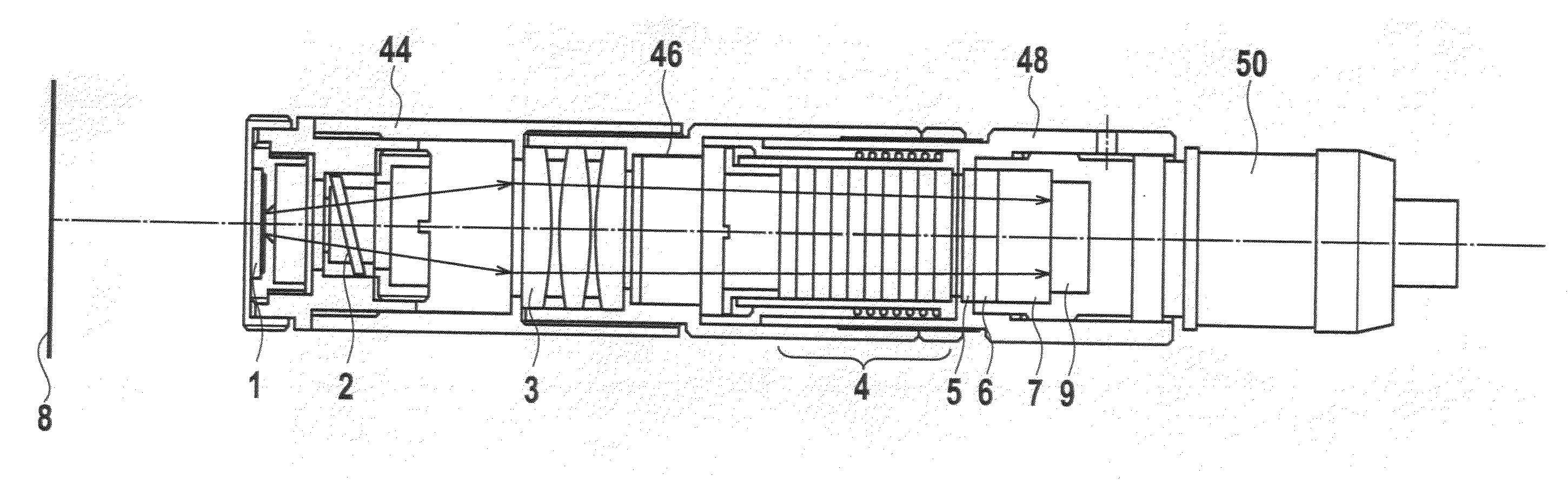
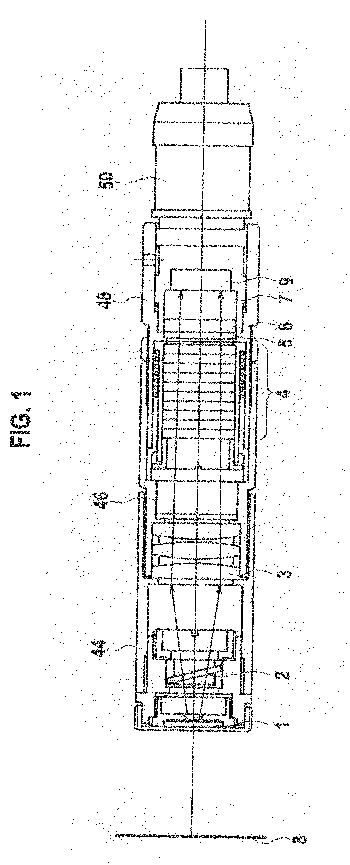
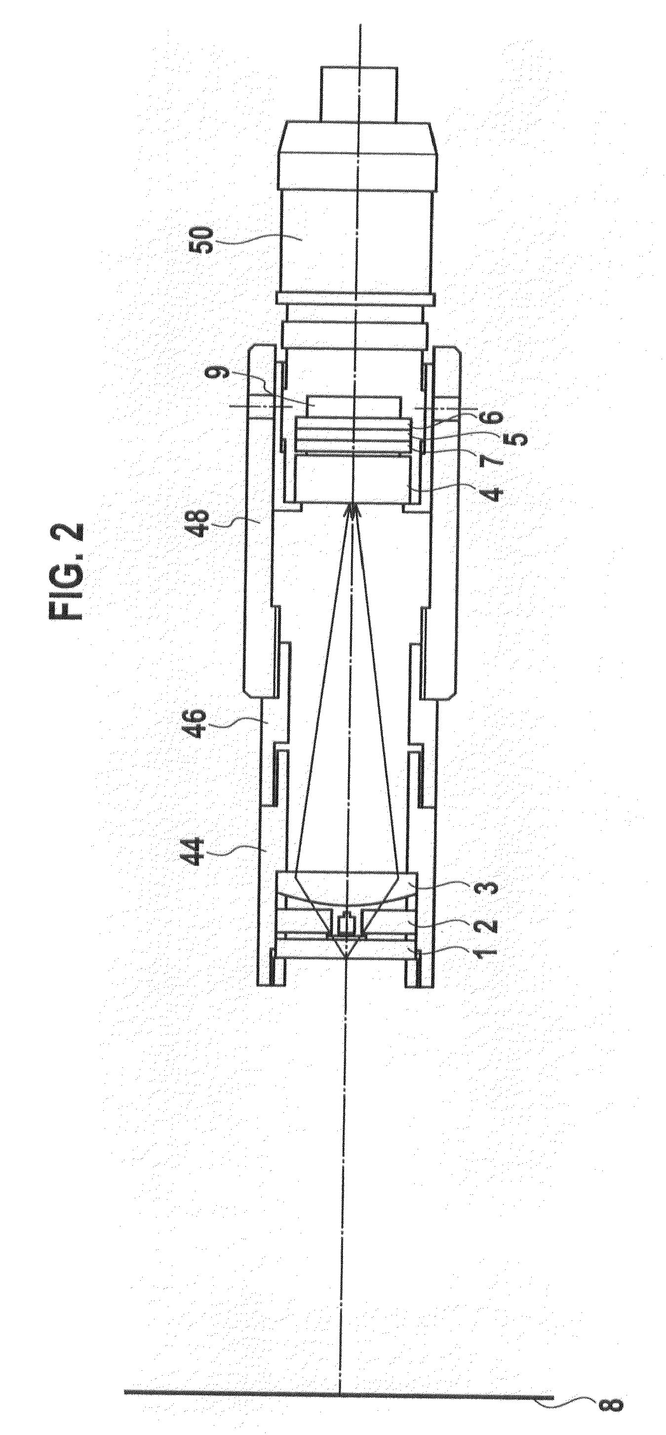
[0071]FIG. 16 shows a schematic cross-section structure of a welding observation apparatus according to a modified example of the first embodiment of the present invention. For example, when observing high power light, pulsed light, etc. in the welding of MIG, MAG, etc., it is available to combine a method of optical shielding in a wavelength region when the arc light cannot be dimmed only at darkening spatial (when the dimming characteristics are insufficient).

[0072]As shown in FIG. 16, the welding observation apparatus according to the modified example of the first embodiment of the present invention includes: an arc welding unit 8; an objective optical system including a the window unit 1 for concentrating the light from the arc welding unit 8, and a first colour filter 2 for illuminating with the light concentrated by the window unit 1; a telecentric optical system (3) for guiding the light passing through the first colour filter 2; a PCF 4 fo...

second embodiment

[0090]FIG. 17 shows a schematic cross-section structure of a welding observation apparatus according to a second embodiment of the present invention. Moreover, FIG. 18 shows a whole configuration of the welding observation apparatus according to the second embodiment of the present invention.

[0091]As shown in FIG. 18, the whole configuration of the welding observation apparatus according to the second embodiment of the present invention includes an objective optical system 52, an image fiber 54 connected to the objective optical system 52, a camera unit 56 connected to the image fiber 54, and a camera control unit 60 connected to the camera unit 56.

[0092]The welding observation apparatus according to the second embodiment of the present invention has a configuration which replaces the telecentric optical system (3) in the first embodiment by an image fiber 54, and other configurations are the same as that of the welding observation apparatus according to the first embodiment. Accord...


PUM

PropertyMeasurementUnit
Wavelengthaaaaaaaaaa
Luminescence spectrumaaaaaaaaaa
Photochromicaaaaaaaaaa

Abstract

A welding observation apparatus is provided to use partial darkening by a telecentric optical system and a photochromic filter (PCF) as an optical system for filtering light emission from arc discharge in order to verify the welding condition under the welding arc discharge, without forming an image on the PCF, so that light reducing performance can be secured even if a focus shifts from on the PCF, with satisfactory monitoring of welding condition.
The welding observation apparatus comprises: an arc welding unit 8; an objective optical system (1, 2) for concentrating light from the arc welding unit 8; a telecentric optical system 3 for guiding the light concentrated by the objective optical system (1, 2); a PCF 4 for illuminating with the light guided by the telecentric optical system 3; and a solid state imaging device 9 for receiving the light passing through the PCF 4, wherein the light from the arc welding unit 8 is partial-darkened by the PCF 4.

Description

TECHNICAL FIELD[0001]The present invention relates to a welding observation apparatus, and in particular, relates to a welding observation apparatus having the characteristic in an optical system for filtering light emission from arc discharge in order to verify a welding condition under a welding arc discharge.BACKGROUND ART[0002]There are a TIG (Tungsten Inert Gas Welding) method, a MIG (Metal Inert Gas Welding) method, a MAG (Metal Active Gas Welding) method, etc. in arc welding, for example. Moreover, there area CO2 gas arc welding method (MAG) etc.[0003]The TIG method is a method of generating an arc between a tungsten electrode and a base material in the inert gas atmosphere, such as argon or a helium, and welding by melting a base material and a wedding rod (or welding filler rod) using this arc heat. The tungsten electrode only generates the arc, and does not perform melting shift itself.[0004]In the MAG method, when the welding is started, a welding wire is provided continu...

Claims


Application Information

Patent Timeline
IPC IPC(8): B23K9/16B23K9/00
CPCB23K9/0956B23K9/321B23K31/125Y10S901/42G02B5/208G02B5/23G02B13/22G01N21/67G01N21/71G02B5/28
Inventor NAKATATE, KENICHITSUMANUMA, TAKASHIKATOU, SATOSHIKATOU, AKEMIYAMAGISHI, JUN
Owner THE FUJIKURA CABLE WORKS LTD
Why Eureka
Try Eureka