Method for processing TOPS (Terrain Observation by Progressive Scan)-SAR (Synthetic Aperture Radar)-Raw Data

a technology of synthetic aperture radar and tops, applied in the field of tops observation by progressive scan, can solve the problems of inefficiency and imprecision, increase computational expenditure, inefficiency and imprecision of specan method improved by azimuth scaling, etc., and achieve the effect of high precision and very efficien

Active Publication Date: 2010-08-19
DEUTSCHES ZENTRUM FUER LUFT & RAUMFAHRT EV
View PDF8 Cites 36 Cited by
  • Summary
  • Abstract
  • Description
  • Claims
  • Application Information

AI Technical Summary

Benefits of technology

[0030]It is an object of the present invention, in a method for processing of TOPS-SAR-raw data into image data, to perform this processing in an interpolation-free, highly precise and very efficient manner while avoiding azimuth aliasing (backfolding) and further disadvantages which would otherwise occur in the processing of TOPS raw signals.

Problems solved by technology

The above explained processor which is specially provided for the TOPS mode has the disadvantage of requiring pre- and post-processing steps so as to be able to handle the peculiarities of the TOPS signal, which will cause an increase of the computational expenditure.
The multi-rate filter band requires that the data be processed in small blocks in the azimuth time with a certain overlap, thus causing inefficiency and imprecision when the azimuth processing is performed.
Particularly, the SPECAN method improved by azimuth scaling is not efficient, which is due to the fact that the focused image is obtained after a direct Fourier transformation (it is focused in the range Doppler region).
Otherwise, the processing would become inefficient.
In the TOPS case, however, the aliasing will occur with certainty because the scene size for a burst is normally rather large.
Azimuth block processing could be an option in order to focus the images with the aid of the SPECAN method improved by azimuth scaling; however, this solution is inefficient.
Another possibility could reside in increasing the PRF scan prior to the azimuth scaling operation by means of zero padding; however, also here, the computational expenditure would increase and the processing would be inefficient.
The original azimuth scaling approach does not constitute an efficient solution which would be applicable for the TOPS mode and the sliding spotlight mode for the purpose of azimuth sidelobe suppression.
This, however, will require that all targets are situated in the base band so that, consequently, this approach is not an option for the TOPS mode and the sliding spotlight mode.

Method used


Image

  • Method for processing TOPS (Terrain Observation by Progressive Scan)-SAR (Synthetic Aperture Radar)-Raw Data
  • Method for processing TOPS (Terrain Observation by Progressive Scan)-SAR (Synthetic Aperture Radar)-Raw Data
  • Method for processing TOPS (Terrain Observation by Progressive Scan)-SAR (Synthetic Aperture Radar)-Raw Data

Examples


Embodiment Construction

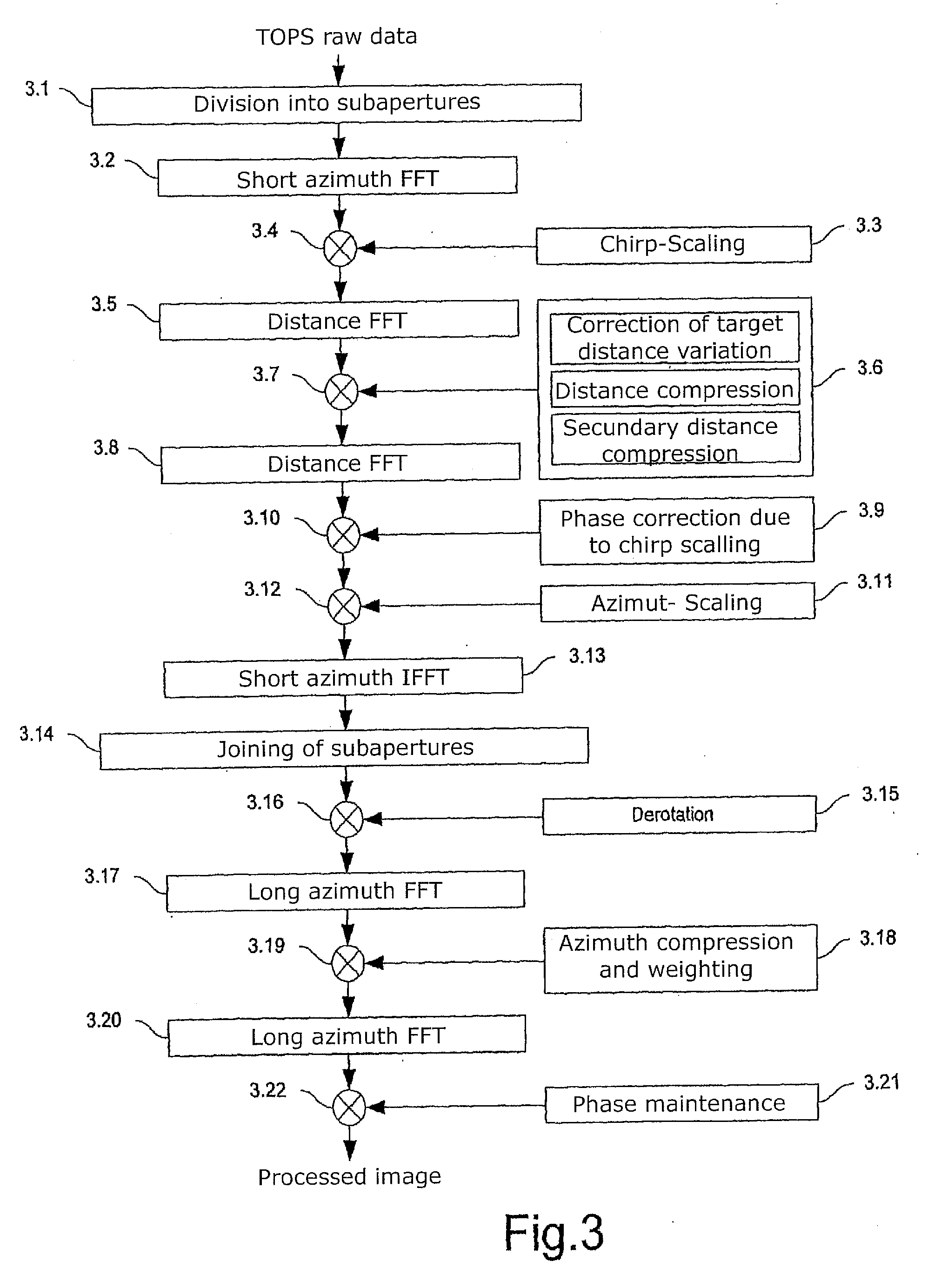
[0050]FIG. 3 is a schematic flowchart showing the individual procedural steps according to a preferred embodiment of the present invention. In the equations related to FIG. 3, t denotes the time vector in the azimuth direction (i.e. the “slow” time), τ denotes the time in the distance direction also referred to as the range direction (i.e. the echo propagation time), fa denotes the azimuth frequency vector (i.e. the Doppler frequency), fr denotes the range frequency, r0 denotes the distance to a point target, r denotes the range vector, λ denotes the wavelength, c denotes the light velocity and v denotes the speed on the ground.

[0051]In step 3.1, the TOPS raw data are first subdivided into subapertures. This subdivision is similar to the one performed in the spotlight processing according to the already mentioned patent specification EP 0 924 534 B1. During the processing, the azimuth bandwidth Ba of a point target, which depends on the antenna beam width, has to be sufficiently sca...


PUM


Abstract

Sub-aperture processing is carried out. Within each sub-aperture, range compression and a correction for the target range variation are carried out. Baseband azimuth scaling is used for processing the azimuth signal, wherein a long azimuth reference function and thus a wide azimuth dimension are prevented. The scaling range is not constant and depends on the range, which is not equal to the original range vector. It is calculated such that, in combination with a subsequent derotation step, constant azimuth scanning is achieved for all ranges. The selected derotation function, which is applied in the azimuth time domain, makes it possible for all the targets to be in base band, in this way varying the effective chirp rate. Since the phase is purely quadratic because of the azimuth scaling step, it is thus possible to use an optimal filter which takes account of the effective chirp rate. IFFT results in a focused image, and a final phase function in the time domain allows phase maintenance. Application for SAR, SONAR and seismic raw data processing in the TOPS mode, as well as other modes which make use of the antenna polar diagram being scanned in the azimuth and / or elevation direction.

Description

TECHNICAL FIELD[0001]The invention relates to a method for processing TOPS (Terrain Observation by Progressive Scan)-SAR(Synthetic Aperture Radar)-Raw Data into highly accurate image data.[0002]First, a brief introduction into SAR and TOPS-SAR will be rendered hereunder. A radar with synthetic aperture, abbreviated SAR (Synthetic Aperture Radar), is an instrument for remote sensing which is increasingly finding application in imaging, surveyance and examination of the surface of the earth. Such a system consists of a carrier platform moving over the surface of the earth at a constant speed, an antenna facing into a direction orthogonal to the moving direction, and a coherent radar system for periodic emission of pulses of high-frequency electromagnetic waves at a pulse repetition frequency PRF.[0003]The direction of the movement of the carrier platform is called the azimuth direction, and the orthogonal direction, oriented diagonally downward, is called the distance direction or als...

Claims


Application Information

Patent Timeline
Patent Type & Authority Applications(United States)
IPC IPC(8): G01S13/90
CPCG01S13/9094G01S13/9035G01S13/904G01S13/9056
Inventor PRATS, PAUMITTERMAYER, JOSEFSCHEIBER, ROLFMOREIRA, ALBERTO
Owner DEUTSCHES ZENTRUM FUER LUFT & RAUMFAHRT EV
Why Eureka
Try Eureka