Blood vessel ultrasonic image measuring method

a blood vessel and ultrasonic technology, applied in tomography, instruments, applications, etc., can solve the problems of difficult to follow the movement and lack of skill, and achieve the effect of facilitating positioning, accurate acquisition of blood vessel diameter, and simple and easy positioning

Active Publication Date: 2010-08-19
UNAX CORP
View PDF5 Cites 41 Cited by
  • Summary
  • Abstract
  • Description
  • Claims
  • Application Information

AI Technical Summary

Benefits of technology

[0019]According to the blood vessel ultrasonic image measuring method of the first mode of the invention, the method includes (d) an around-X-axis positioning step of causing the positioning device to position the ultrasonic probe around the X-axis such that distance from the first short axis ultrasonic array probe to center of the blood vessel becomes equal to distance from the second short axis ultrasonic array probe to the center of the blood vessel; (e) an X-axis direction positioning step of causing the positioning device to translate the ultrasonic probe in the X-axis direction such that an image of the blood vessel is positioned at a center portion in width direction of the first short axis image display area; and (f) an around-Z-axis positioning step of causing the positioning device to rotate the ultrasonic probe around the Z-axis such that an image of the blood vessel is positioned at a center portion in width direction of the second short axis image display area. Consequently, the positioning may be performed by using the positions in the longitudinal direction of the ultrasonic array probes relative to the blood vessel or the distances of the ultrasonic array probes to the blood vessel and, therefore, the ultrasonic probe may simply and easily be positioned on the blood vessel of the living body with higher accuracy.
[0020]According to the blood vessel ultrasonic image measuring method of the second mode of the invention, (g) the X-axis is an axis passing under the skin, wherein (h) at the around-X-axis positioning step, the ultrasonic probe is positioned around the X-axis. Consequently, the condition of pressing the skin by the first short axis ultrasonic array probe and the second short axis ultrasonic array probe may not significantly be changed to change the distances between the probes and the blood vessel. Preferably, the X-axis is located immediately under the first short axis ultrasonic array probe. In this case, almost no change is made in the condition of pressing the skin by the first short axis ultrasonic array probe and the distance between the first short axis ultrasonic array probe and the blood vessel.
[0021]According to the blood vessel ultrasonic image measuring method of the third mode of the invention, (i) the ultrasonic probe further includes a long axis ultrasonic array probe abutting on the fir

Problems solved by technology

However, since the ultrasonic probe is positioned by manual operation of an operator, a lot of s

Method used


Image

  • Blood vessel ultrasonic image measuring method
  • Blood vessel ultrasonic image measuring method
  • Blood vessel ultrasonic image measuring method

Examples


first embodiment

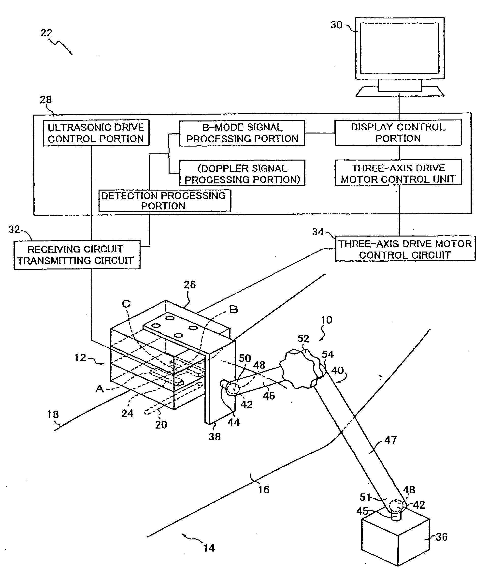
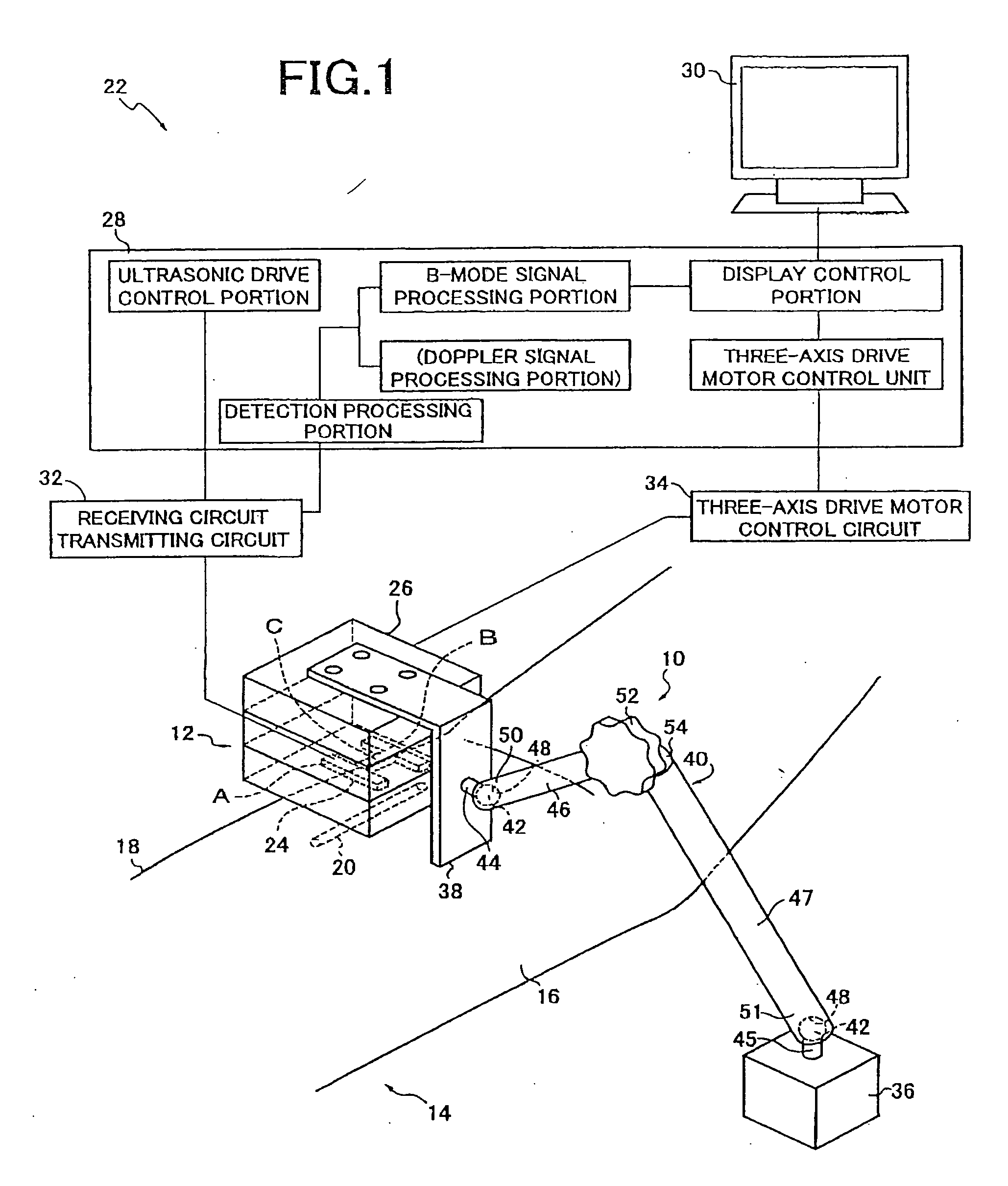
[0089]FIG. 1 is a diagram for explaining an overall configuration of a blood vessel ultrasonic image measuring apparatus 22 using a hybrid probe unit 12 held by a sensor holder 10 to measure a cross-section image (short axis image) or a longitudinal-section image (long axis image) of a blood vessel 20 located immediately below skin 18 from the top face of the skin 18 of an upper arm 16 of a living body 14.

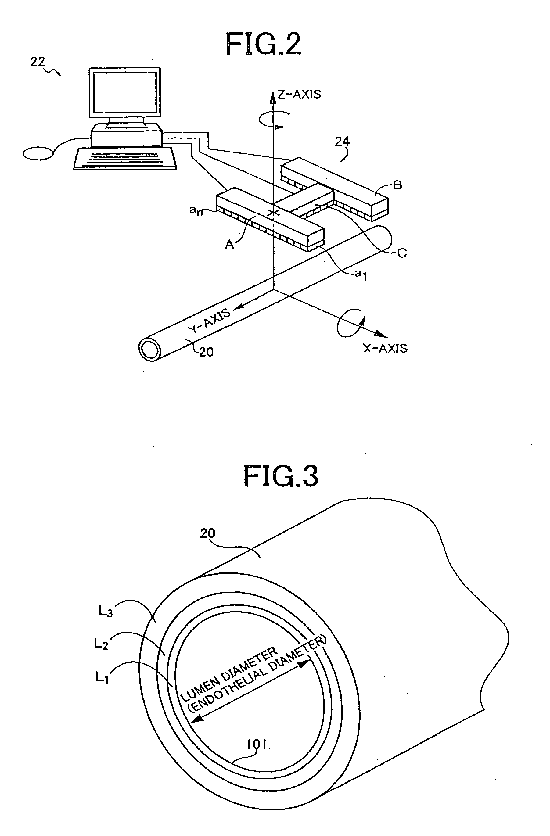
[0090]The hybrid probe unit 12 acts as a sensor for detecting biological information related to the blood vessel, i.e., a blood vessel parameter and includes an H-shaped ultrasonic probe 24 made up of two lines of a first short axis ultrasonic array probe A and a second short axis ultrasonic array probe B parallel to each other and a long axis ultrasonic array probe C linking the longitudinal center potions thereof on one flat surface, i.e., a flat probing surface 27, and a multiaxis driving device (positioning device) 26 for positioning the ultrasonic probe 24. The first short axi...

second embodiment

[0115]Another embodiment of the present invention will then be described. In the description of the following embodiment, the portions overlapping with the embodiment are denoted by the same reference numerals and will not be described.

[0116]FIG. 25 is a diagram for explaining exemplary configurations of the ultrasonic probe and the monitor screen display in another embodiment of the present invention. The hybrid probe unit 12 of this embodiment includes an H-shaped ultrasonic probe 102 made up of two lines of the first short axis ultrasonic array probe A and the second short axis ultrasonic array probe B parallel to each other and rotated around the X-axis such that directions F orthogonal to the ultrasonic emitting surfaces of the ultrasonic transducers a1 to an configured by linear arrangement in the X-axis direction are respectively tilted by predetermined angle α and angle β relative to the Z-axis; and the long axis ultrasonic array probe C configured by linearly arranging the ...

third embodiment

[0120]FIGS. 26 and 27 are flowcharts for explaining a portion of a relevant part of the control operation of the electronic control device 28 in another embodiment of the present invention. Although the artery pattern recognition is performed at steps depicted in the flowcharts of FIGS. 10 and 11 in the embodiment, if the electronic control device 28 includes a Doppler signal processing portion, the artery pattern recognition is performed at steps depicted in the flowcharts of FIGS. 26 and 27 instead of FIGS. 10 and 11. In FIG. 26, at step S26, the ultrasonic oscillation and scanning are started and the convergent ultrasonic beam is emitted from the first short axis ultrasonic array probe A, the second short axis ultrasonic array probe B, and the long axis ultrasonic array probe C and is also scanned. At step S27, an image pattern similar to the standard template TM1 is searched by using the template matching technique in the first short axis image display area G1. At S28, the match...


PUM


Abstract

A blood vessel ultrasonic image measuring method capable of facilitating the positioning of an ultrasonic probe and acquiring sufficient positioning accuracy is provided. Because of inclusion of an around-X-axis positioning step of causing a multiaxis driving device 26 to position an ultrasonic probe such that distances from respective ultrasonic array probes to the center of a blood vessel are equalized, and an X-axis direction positioning step and an around-Z-axis positioning step of causing the multiaxis driving device to position the ultrasonic probe such that the image of the blood vessel is positioned at the center portion in the width direction of the first short axis image display area G1 and the second short axis image display area G2, the positioning may be performed by using the positions in the longitudinal direction of the ultrasonic array probes relative to the blood vessel or the distances of the ultrasonic array probes to the blood vessel and, therefore, the ultrasonic probe may simply and easily be positioned on the blood vessel of a living body with higher accuracy.

Description

TECHNICAL FIELD[0001]The present invention relates to a blood vessel ultrasonic image measuring method, which accurately positions an ultrasonic probe on a blood vessel of a living body.BACKGROUND ART[0002]An ultrasonic array probe having a plurality of ultrasonic transmitters linearly arranged is used for measuring a diameter of a blood vessel under skin of a living body. For example, Patent Document 1 proposes an apparatus that uses and H-shaped ultrasonic probe made up of a first and second ultrasonic array probes in parallel with each other and a third ultrasonic array probe linking the intermediate potions thereof to measure a blood flow velocity, arterial vessel wall thickness and lumen diameter, etc., by positioning the third ultrasonic array probe in parallel with an arterial vessel. However, since the ultrasonic probe is positioned by manual operation of an operator, a lot of skill is required and, if a subject moves, it is problematically difficult to follow the movement.D...

Claims


Application Information

Patent Timeline
IPC IPC(8): A61B8/14
CPCA61B5/489A61B5/6835A61B8/4281A61B8/4483G01S7/52065A61B8/488G01S15/8936A61B8/4494A61B8/0891A61B8/4218A61B8/464G01S15/8925
Inventor HARADA, CHIKAOMASUDA, HIROSHISUZUKI, HIDENORI
Owner UNAX CORP
Why Eureka
Try Eureka