
Ultrasonic flaw detection method and ultrasonic flaw detection equipment

Active Publication Date: 2010-08-26
KRAUTKRAMER JAPAN
View PDF6 Cites 21 Cited by
  • Summary
  • Abstract
  • Description
  • Claims
  • Application Information

AI Technical Summary

Benefits of technology

[0056]Through an intensive study, the inventors aim to prevent the occurrence of the above-described dead zone in a material being tested, the material in the shape of a rectangular column and having a rectangular cross-sectional shape, while reducing flaw detection time by using volume focusing flaw detection.

Problems solved by technology

However, as is the case with multimode flaw detection, a temporal restriction is put on this method because transmission and reception is performed on a cycle-by-cycle basis.
This problem is similar to that of a single probe.
However, in either method, there is a limit to a speedup since the method performs (electronic) scanning while making each virtual probe transmit and receive ultrasonic waves.
Furthermore, since a large aperture cannot be formed in the current virtual probe having about 16 to 32 channels, making it impossible to lengthen the focal length.
Thus, there is a limit to flaw detection of a thick and large object.
Moreover, signals obtained by the vibration due to the reception performed by these 32 elements are also delayed individually.
However, in zone focusing, since the next T2 is transmitted for the same cross section of the material being tested as the cross section to which T1 is transmitted, transmission of T2 cannot be performed until a ghost echo of T1 disappears.
However, in particular, when internal flaw detection of a metal rod in the shape of a rectangular column, the metal rod called a square billet and having a rectangular cross-sectional shape, is performed, the presence of a dead zone in which adequate flaw detection cannot be performed becomes a problem (for conventional flaw detection of a square billet, see Nonpatent Literatures 3 and 4).
However, in reality, due to a reflection echo (a front surface echo) generated on the above-described incident side (an upper side), a region near the incident side in the square billet is a dead zone (a dead band) in which it is difficult to detect a defective echo.

Method used


Image

  • Ultrasonic flaw detection method and ultrasonic flaw detection equipment
  • Ultrasonic flaw detection method and ultrasonic flaw detection equipment
  • Ultrasonic flaw detection method and ultrasonic flaw detection equipment

Examples


Embodiment Construction

[0094]Hereinafter, an embodiment of the invention will be described based on the drawings.

[0095]The embodiment of the invention is shown in FIGS. 1 to 9.

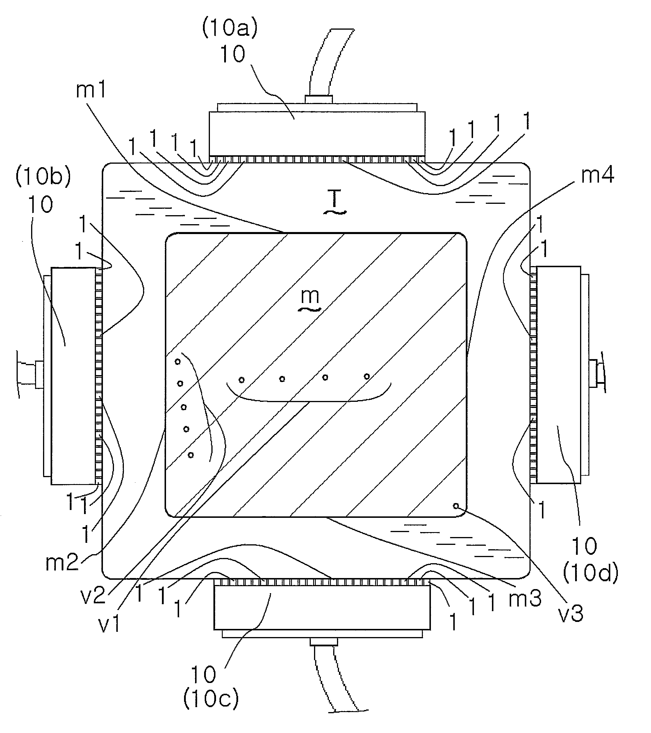
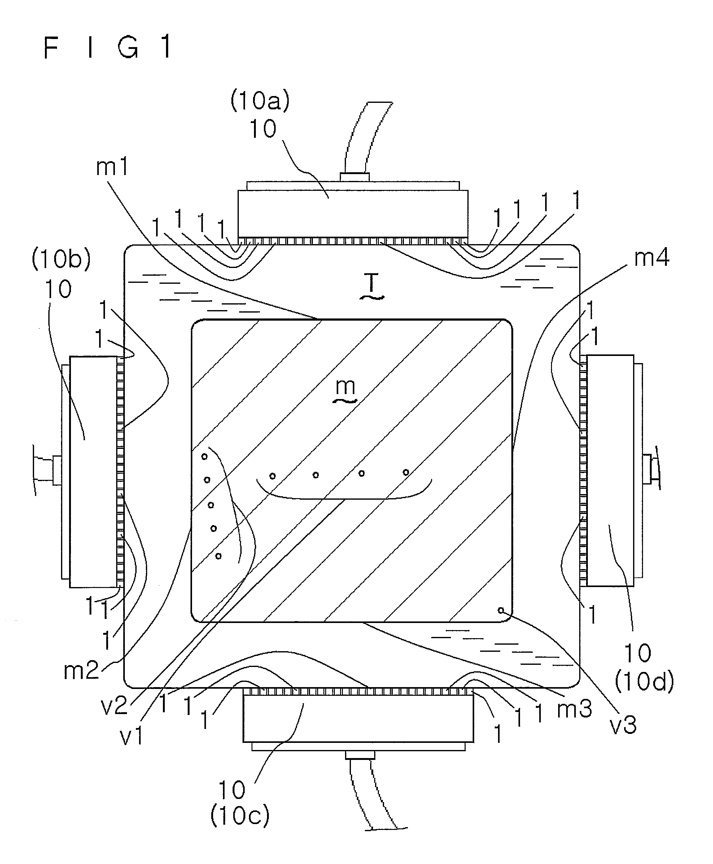
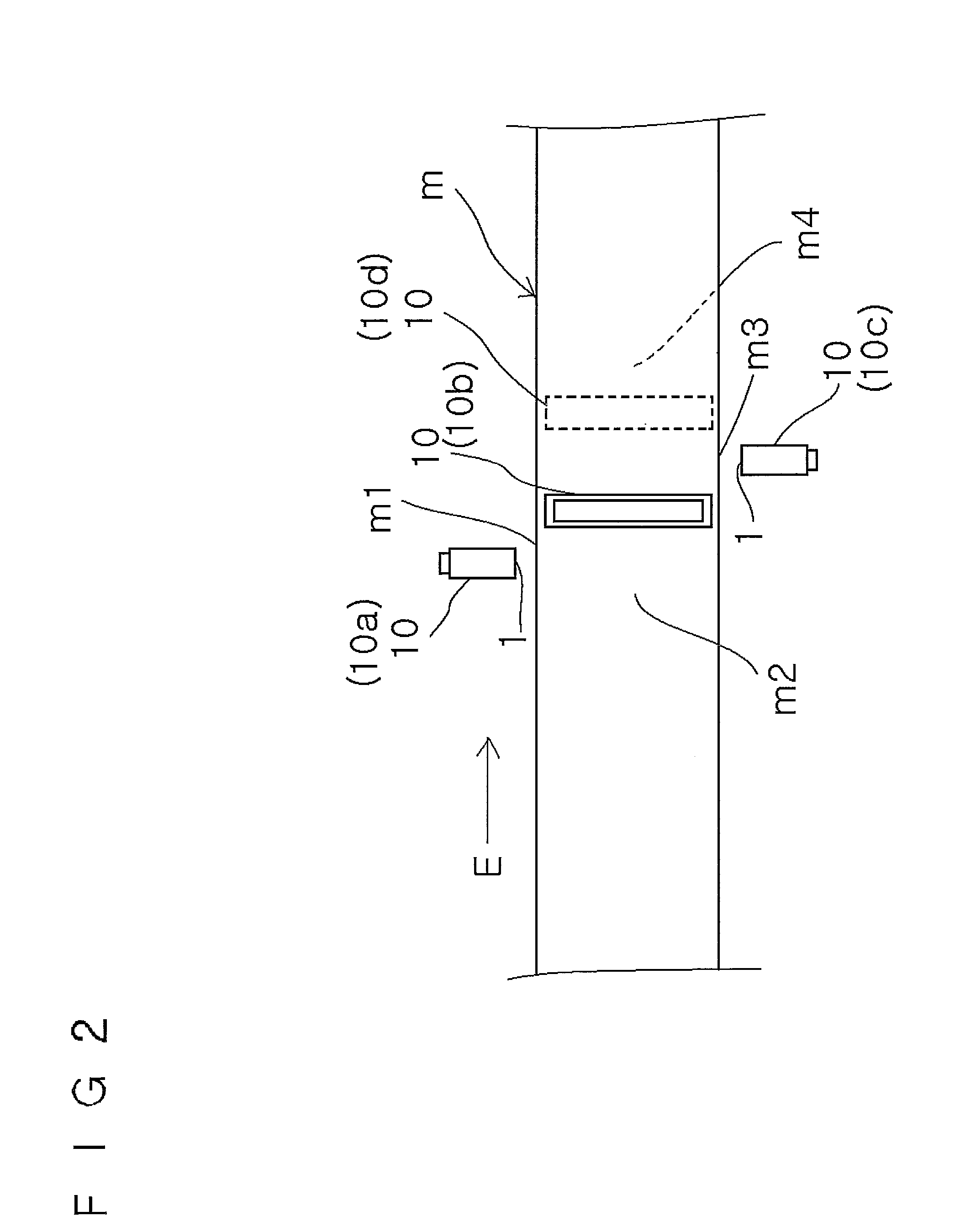
[0096]FIG. 1 is a schematic sectional view showing the placement of array probes of equipment in accordance with the embodiment of the invention. FIG. 2 is a schematic side view showing the above placement. FIG. 3 is a block diagram of the equipment. FIG. 4 is a block diagram of an enlarged principal portion of the block diagram of FIG. 3. FIG. 5 is a schematic sectional view showing a state in which one array probe of the above equipment emits ultrasonic waves toward a material being tested. FIG. 6 is an explanatory diagram of oblique flaw detection performed by the above equipment. FIG. 7 is a flow chart showing a control procedure of the above ultrasonic flaw detection equipment. FIG. 8 is an explanatory diagram showing an image of pseudo electronic scanning of the ultrasonic flaw detection equipment. FIG. 9 is an explanatory dia...


PUM


Abstract

Equipment of the invention uses a volume focusing flaw detection method. In a sectional view of a material m being tested, a plurality of transducers 1 . . . 1 of one of array probes 10 are arranged along one side of a rectangular shape of the material being tested, and a plurality of transducers 1 . . . 1 of the other of the array probes 10 are arranged along one of sides adjacent to the one side. An exciting unit makes each array probe emit ultrasonic waves by a vertical flaw detection method and an oblique flaw detection method in such a way as to allow the ultrasonic waves to enter the material being tested from each position on an incident side, which is a side along which the array is placed, as a result of the plurality of transducers being vibrated once, makes the ultrasonic waves allowed to enter by the vertical flaw detection method reach a counter side facing the incident side, and makes the ultrasonic waves allowed to enter by the oblique flaw detection method reach one of adjacent sides adjacent to the incident side, and the exciting unit sets no actual focus of the ultrasonic waves in the material being tested.

Description

TECHNICAL FIELD[0001]The present invention relates to an ultrasonic flaw detection method and ultrasonic flaw detection equipment.BACKGROUND ART[0002]Patent Document 1: JP-A-2003-130859[0003]Patent Document 2: Japanese Patent No. 3704065[0004]Nonpatent Literature 1: Takeko Murakami, Dominique Braconnier, Shunji Miura, Junichi Murai, Yutaka Nishitani, Proceedings of the 13th Symposium on Ultrasonic Testing, pp. 33-38, (2006)[0005]Nonpatent Literature 2: Yoshikazu Yokono, Present Situation of Standardization of Phased Array UT, NDI Document 21776, pp. 34-38 (2006)[0006]Nonpatent Literature 3: Masashi Mizuno, Hisao Nakase, Hiro Koda, Non-Destructive Inspection (Journal of the Japanese Society for Non-Destructive Inspection), 37(11), pp. 861-868, (1988)[0007]Nonpatent Literature 4: Ultrasonic Flaw Detection of Steel, edited by the Iron and Steel Institute of Japan, Joint Research Group, Committee of Non-Destructive Inspection under Quality Control Society, pp. 79, (1993)[0008]In a conve...

Claims


Application Information

Patent Timeline
IPC IPC(8): G01N9/24G01N29/04
CPCG01N29/043G01N29/221G01N2291/106G01N29/4454G01N29/262
Inventor MURAI, JUNICHIBRACONNIER, DOMINIQUE
Owner KRAUTKRAMER JAPAN
Learn More