Non-planar adaptive wing solar aircraft

a solar aircraft and adaptive technology, applied in the field of solar powered aircraft, can solve the problems of control system instability, failure of wing covering, and especially critical night time power usag

Inactive Publication Date: 2010-08-26
AURORA FLIGHT SCI CORP
View PDF19 Cites 46 Cited by
  • Summary
  • Abstract
  • Description
  • Claims
  • Application Information

AI Technical Summary

Benefits of technology

[0019]According to the first aspect, the wing panel comprises: an upper and lower surface, wherein one or both of the upper and lower surfaces includes one or more photovoltaic cells, wherein each of the one or more photovoltaic cells is configured to convert solar radiation energy into electricity. Still further according to the first aspect, the control system is further configured to alter the angle between the first and second wing panels to substantially maximize collection of solar radiation energy.
[0044]According to a fourth aspect of the present invention, an aircraft is provided, comprising: a wing panel, wherein the wing panel includes an upper and lower surface, and wherein one or both of the upper and lower surfaces includes one or more photovoltaic cells, wherein each of the one or more photovoltaic cells is configured to convert solar radiation energy into electricity; and a control system, wherein the control system is configured to acquire aircraft information and atmospheric information, and further wherein the control system is configured to use the acquired aircraft information and atmospheric information to alter the angle between the wing panel and a horizon, to substantially maximize collection of solar radiation energy.

Problems solved by technology

Sunrise II flew successfully, but broke up in flight at 22,000 ft due to a suspected aeroelastic problem.
The in-flight break-up was caused when a gust-induced aeroelastic wing shape change led to a control system instability.
The resulting pitch oscillation resulted in excessive speeds which caused failure of the wing covering.
As discussed in great detail below, night time power usage is especially critical, because the storage system is quite heavy, and there is a storage “round trip” efficiency.
This means that a large amount of solar energy must be collected to provide even a small amount of power at night.
However, a significant limitation of the airplane disclosed in the Hibbs patent is that it is poor at collecting energy during the winter time at high latitudes.
Another significant limitation is that at high latitudes, the aircraft must fly predominantly towards the west, so the sun, at peak elevations, will be predominantly off the left wingtip.
The poor collection geometry of the airplane disclosed in the Hibbs patent (i.e., the horizontal solar panels), combined with short days and long nights makes it very difficult for the Hibbs' airplane to collect enough solar energy.
While the cruciform configuration disclosed in the Phillips patent provides improved solar energy collection than the configuration shown in the Hibbs patent, it has twice as much wing area as is needed to produce lift, and thus incurs a significant penalty in drag and thus energy required to fly, especially during the night (when no solar radiation energy collection can occur).
This is good for typical westerly winds, but for the occasional easterly winds, cells would be needed on both sides of both tips, which is both a mass and cost penalty.
Configuration 14 of FIG. 47 provides solar cells on top of both tips, but is not symmetric, and it was believed that the control systems of the time would not be able to fly the airplane.
As a result, a large downwardly directed load is brought upon the tips of the center section.
Because the tips cannot support their own weight, the fraction of the span that could be pivoted up is limited.
All of the above concepts have some problems with either solar collection at low sun elevation angles, sun collection at medium sun elevation angles, night time energy requirements or excessive structural mass.
Thus, there is a need for a solar aircraft configuration that can effectively adapt to a wide range of sun angles, does not carry collectors that are not useful at some sun angles, has very low drag for low night time energy requirements, and also does not require excessive structural mass, and thus can allocate a large mass to the energy storage system.
While the historical solar powered aircraft have increased flight duration and altitude over time, none have exhibited the ability to fly at high latitudes, nor have any shown greater duration than perhaps a day or two.
Thus, historical solar powered aircraft all have limitations due to poor high latitude solar collection efficiency due to the horizontal nature of their arrays and insufficient energy storage to fly through a long winter night.

Method used


Image

  • Non-planar adaptive wing solar aircraft
  • Non-planar adaptive wing solar aircraft
  • Non-planar adaptive wing solar aircraft

Examples


Embodiment Construction

[0069]The various features of the preferred embodiments will now be described with reference to the drawing figures, in which like parts are identified with the same reference characters. The following description of the presently contemplated best mode of practicing the invention is not to be taken in a limiting sense, but is provided merely for the purpose of describing the general principles of the invention.

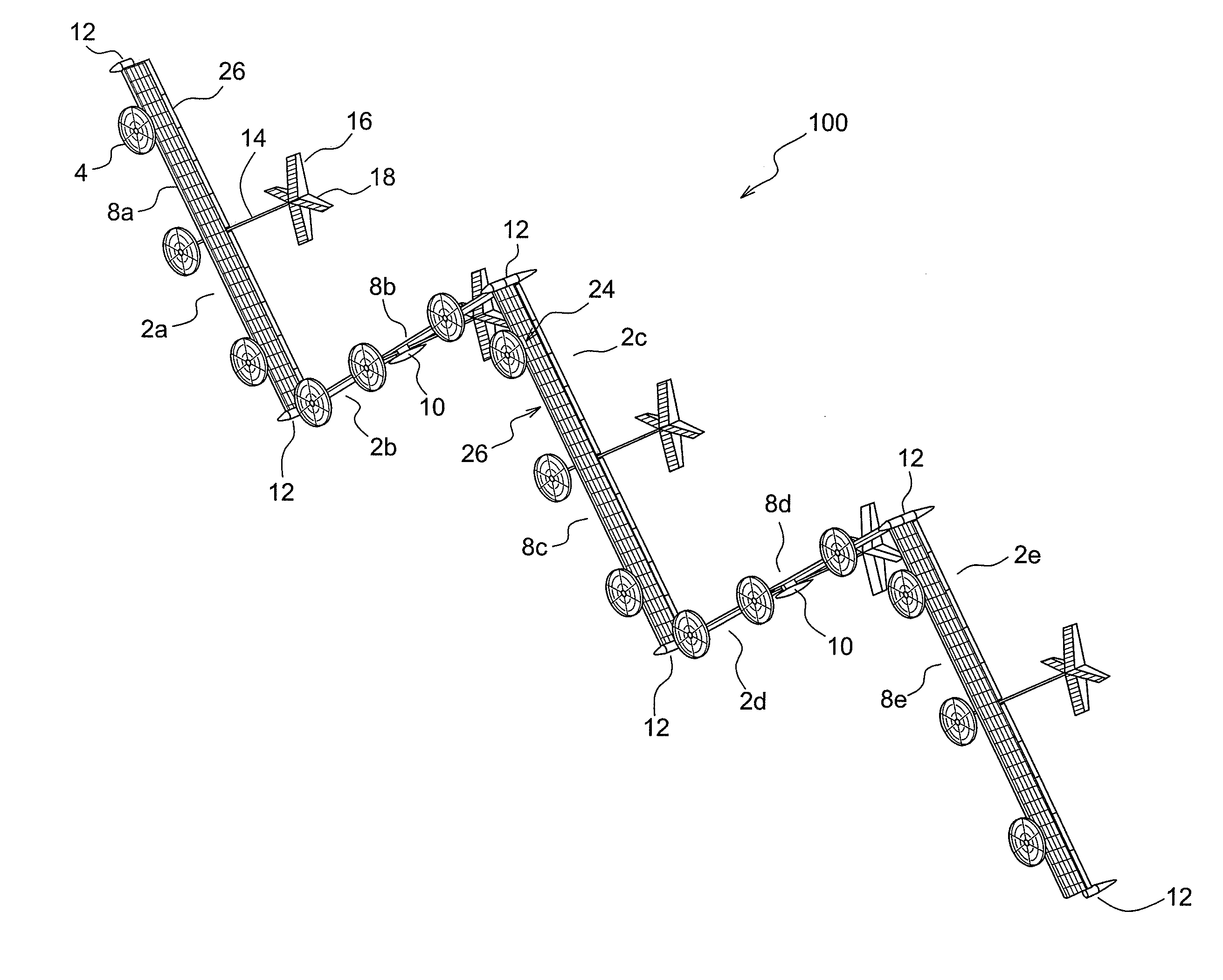
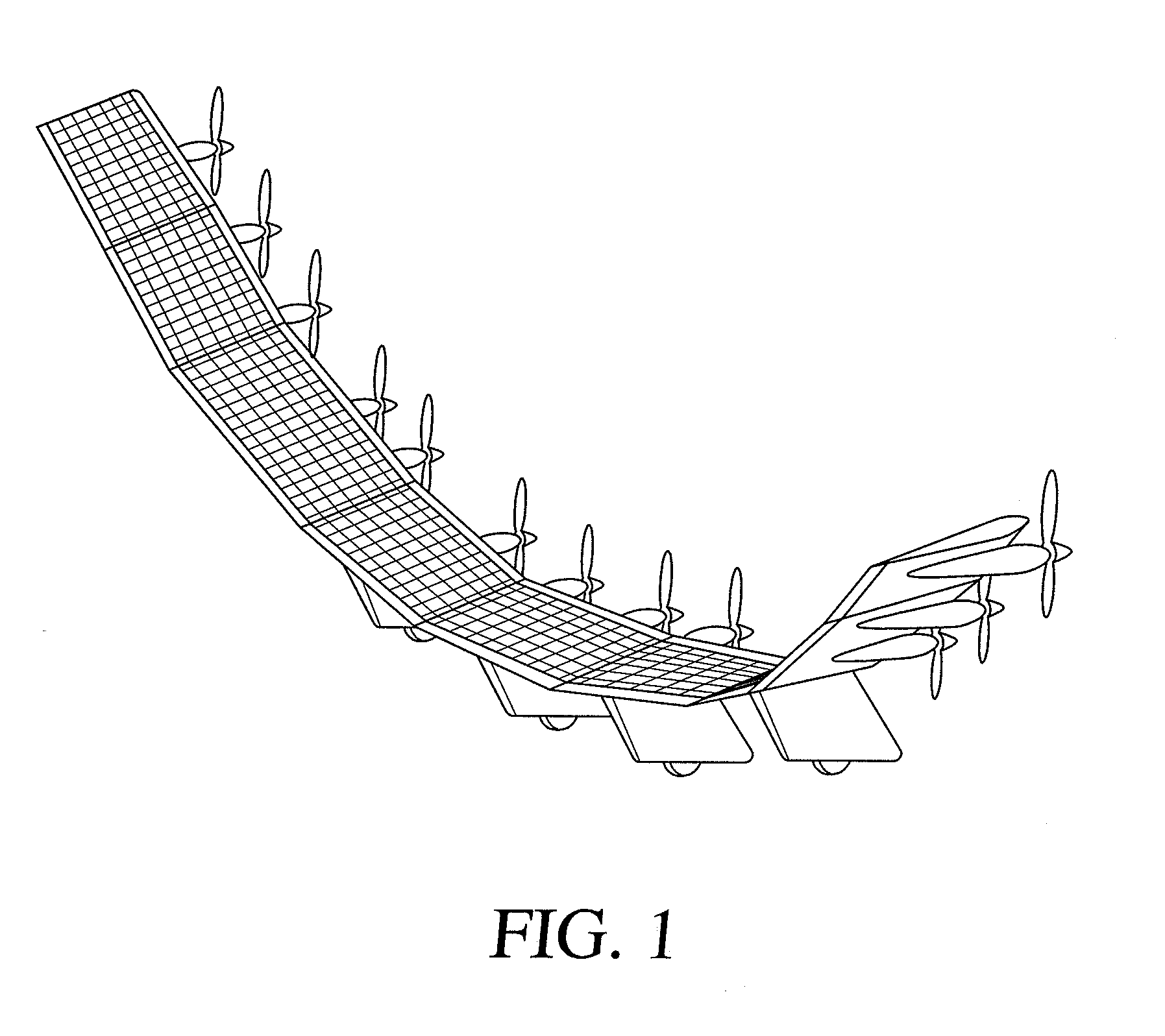
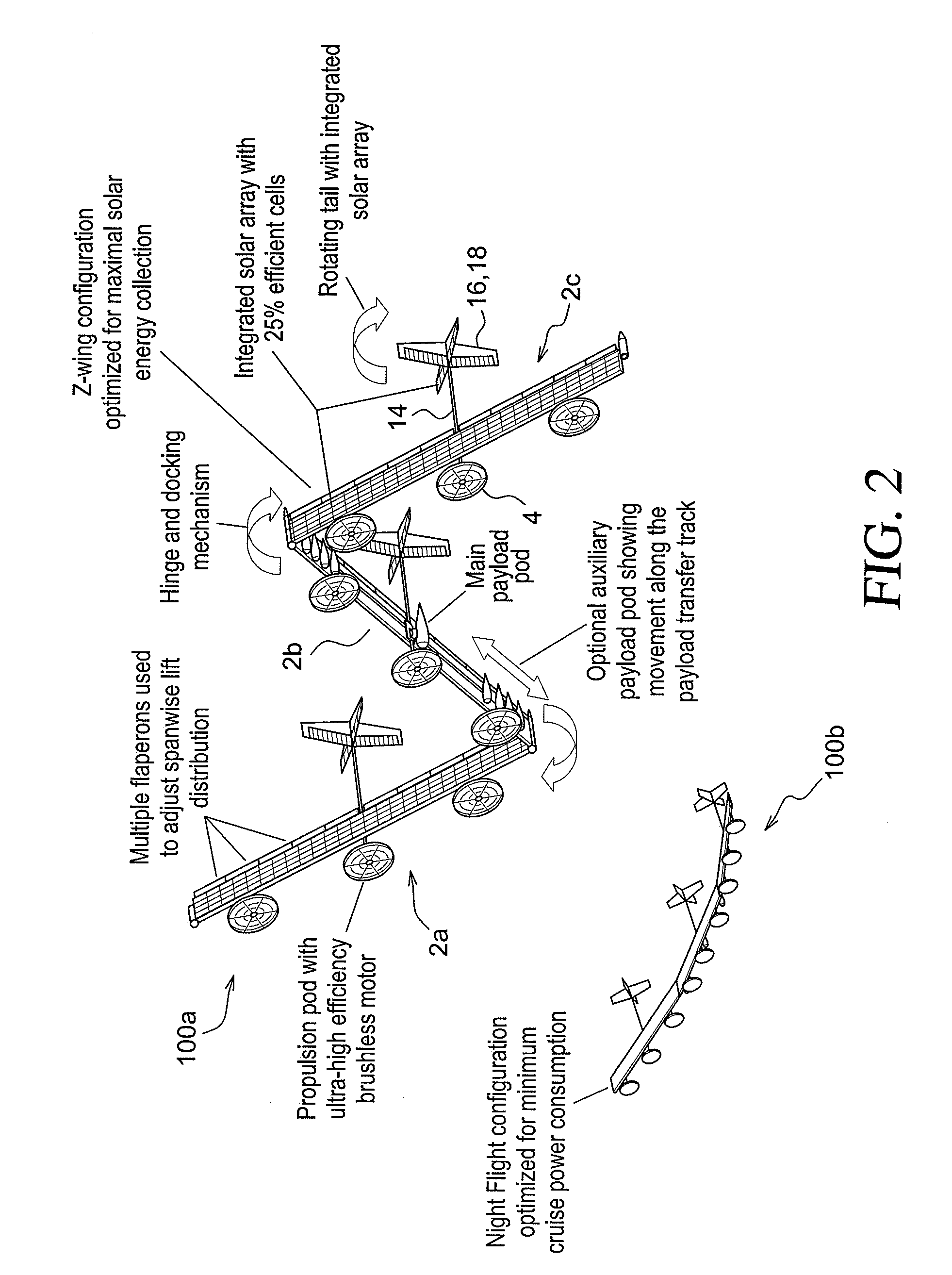
[0070]According to exemplary embodiments, the system and method for a non-planar adaptive wing structure can work on several different types of aircraft. According to a preferred embodiment, the system and method for a non-planar adaptive wing structure can work on a solar powered aircraft. Thus, the discussion below should not be construed to be limited to any one particular type of aircraft. By way of example only, and according to a preferred embodiment, discussion is made of light, unmanned aerial vehicles. More particularly, and according to a preferred embodiment, the d...


PUM


Abstract

A system and method for assembling and operating a solar powered aircraft, composed of one or more modular constituent wing panels. Each wing panel includes at least one hinge interface that is configured to rotationally interface with a complementary hinge interface on another wing panel. When a first and second wing panel are coupled together via the rotational interface, they can rotate with respect to each other within a predetermined angular range. The aircraft further comprises a control system that is configured to acquire aircraft operating information and atmospheric information and use the same alter the angle between the wing panels, even if there are multiple wing panels. One or more of the wing panels can include photovoltaic cells and / or solar thermal cells to convert solar radiation energy or solar heat energy into electricity, that can be used to power electric motors. Further, the control system is configured to alter an angle between a wing panel and the horizon, or the angle between wing panels, to maximize solar radiation energy and solar thermal energy collection. A tail assembly for the aircraft includes a rotational pivot that allows the flight control surfaces to rotate to different orientations to avoid or reduce flutter loads and to increase solar radiation energy and / or solar thermal energy collection from photovoltaic cells and / or solar thermal cells the can be located on the tail structure associated with the flight control surfaces.

Description

PRIORITY[0001]This application claims the benefit of priority under 35 U.S.C. §119(e) from U.S. Provisional Application Ser. No. 60 / 972,720, entitled “NON-PLANAR ADAPTIVE WING SOLAR AIRCRAFT”, filed on Sep. 14, 2007, the entire contents of which are incorporated herein by reference.BACKGROUND OF THE INVENTION[0002]1. Field of the Invention[0003]The invention relates to solar powered aircraft. More particularly, the invention relates to a system and method for altering a configuration of a solar-panel covered wing structure of a solar powered aircraft to increase collection of solar radiation during the day, while also minimizing power consumption at night.[0004]2. Background Art[0005]The concept of high-altitude, long-endurance solar powered aircraft has been demonstrated by a number of air vehicle research projects in the past. In 1974, AstroFlight built the first solar powered drone, Sunrise I. The promising results of the 32 foot span, Sunrise I, led to the Sunrise II, which with...

Claims


Application Information

Patent Timeline
Patent Type & Authority Applications(United States)
IPC IPC(8): B64C39/00B64C3/42B64C9/00B64C3/00B64D27/24
CPCB64C3/16B64D27/24Y02T50/62Y02T50/44Y02T50/12Y02T50/10Y02T50/40Y02T50/60B64C3/38
Inventor PARKS, ROBERT
Owner AURORA FLIGHT SCI CORP
Why Eureka
Try Eureka