

Atmospheric pressure plasma reactor
- Summary
- Abstract
- Description
- Claims
- Application Information
AI Technical Summary
Benefits of technology
Problems solved by technology
Method used
Image


Examples
first embodiment
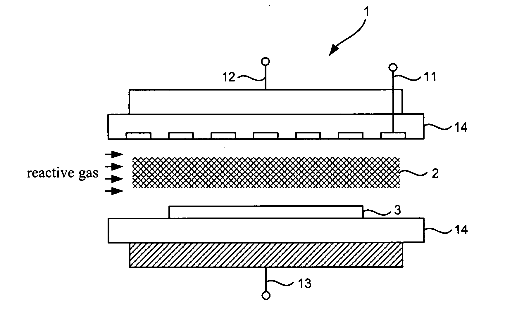
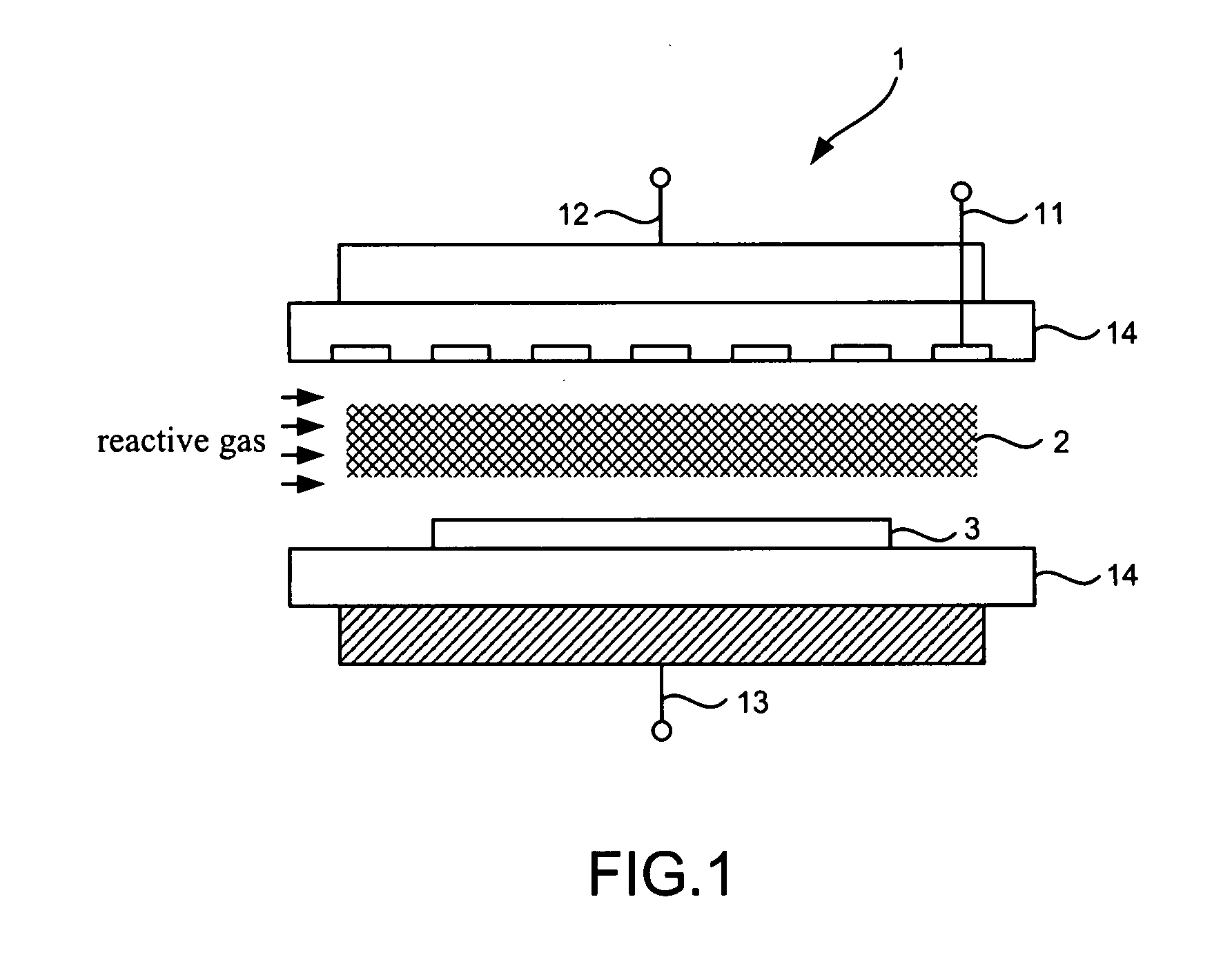
[0024]Referring to FIG. 1, there is shown an atmospheric pressure plasma reactor 1 according to the present invention.
second embodiment
[0025]Referring to FIG. 2, there is shown an atmospheric pressure plasma reactor 1 according to the present invention.
[0026]According to both of the first and second embodiments of the present invention, the atmospheric pressure plasma reactor 1 includes at least one high-voltage electrode 11, a common grounded electrode 12, a bias electrode 13 and two dielectric layers 14. The bias electrode 13 is used to control(s) the energy of ion bombardment, to improve and enhance the surface properties of the treated substrates in activation, cleaning and depositions by minimizing the surface damage and to speed up the treatment processes.
[0027]The high-voltage electrode 11 is electrically connected to an AC, pulsed or RF high-voltage power supply.
[0028]The common grounded electrode 12 is electrically connected to the ground. The common grounded electrode 12 and the high-voltage electrode 11 together generate planar atmospheric pressure plasma 2 in a plasma chamber.
[0029]The bias electrode 13...
PUM
| Property | Measurement | Unit |
|---|---|---|
| Pressure | aaaaa | aaaaa |
| Electric potential / voltage | aaaaa | aaaaa |
Abstract
Description
Claims
Application Information