
Water purification apparatus and system

a technology of water purification apparatus and water purification system, which is applied in the direction of multi-stage water/sewage treatment, filtration separation, separation process, etc., can solve the problems of limited capacity of water purification filter of reasonable size and number, so as to improve the ability to remove dust

Active Publication Date: 2010-09-02
KINETICO
View PDF62 Cites 29 Cited by
  • Summary
  • Abstract
  • Description
  • Claims
  • Application Information

AI Technical Summary

Benefits of technology

[0017]The device described in this application avoids the disadvantages encountered with available carbon block filtration, and is particularly well suited to removal of small particulates, as well as chloramine removal. In particular, the apparatus of the invention substantially limits the amount of dust, whether from activated carbon or other filtration media, imparted to the water being treated, and is better able to remove dust and fine particulates (e.g., ISO 12103-82 0-80 micron dust) when compared to conventional carbon block filtration.
[0020]After leaving the first stage, the water contacts a porous block, which can be made by extrusion molding or by other polymer processing. The block contains purification material, such as active carbon, which has an average particle size ranging from about 80 to about 325 mesh. Without wishing to be bound by any theory, it is believed that the ability of the particulate purification material in the first stage to reduce contaminants, such as chloramines, by approximately 60% to approximately 99% allows the porous block in the second stage to complete the reduction of contaminant to even lower levels. With the use of catalytic carbon in the first stage and carbon block in the second stage, chloramines can be reduced to levels that are not detectable using conventional detection equipment or techniques.

Problems solved by technology

These conventional carbon blocks, while functional, present several disadvantages in use.
First, the capacity of the blocks is limited by the kinetics of adsorption onto the carbon surfaces and into the pores of the bound carbon particles.
Because so much of the surface area of the carbon particles is occluded by binder resin, the capacity of filters of reasonable size and number to treat water is rather limited in terms of volumetric flow rate.
In addition, the total volume of water treated is limited because of clogging of the filter due to the presence of small particulates and other detritus in the water being filtered, as well as because of the saturation of the limited number of active sites on the carbon particulate.
Second, both the volumetric flow rate and the total volume of water treated can be limited by the structural integrity of the carbon block.
Many conventional carbon blocks degrade over a fairly short period of time as the flow of water erodes them, breaking them into smaller blocks that can move around in the flow system and cause clogging.
Third, carbon blocks, in particular extruded carbon blocks, can be difficult to manufacture with high consistency, leading to unpredictable performance results.
The binder resins must be heated, either directly or by shear in an extruder, which can passivate some of the carbon, rendering the blocks less effective.
Fourth, existing carbon block formulations are not particularly effective at removing chloramines, rendering them less than desirable for use in water purification systems used in the food processing industry.
However, the inventor has found that including this material in a carbon block results in a substantial amount of deactivation of the catalytic activity of the carbon, believed to result from the need to heat the binder resin to form the carbon block.
Moreover, chloramine reduction is very complex to achieve by carbon block filters made from regular granulated activated carbon, be it molded or extruded, etc.
Special catalytic carbons have been developed to remove chloramine, but when they have been molded or extruded into carbon block, they lose 90% of their efficiency for chloramine removal.
At this pH level, most carbon loses its removal efficiency quite rapidly, if not immediately.
Since a water filter requires a minimum amount of water flow to function effectively and economically, the size of the filter becomes critical.
Carbon block filtration results in other disadvantages as well.
It is often difficult to prepare carbon blocks with adequate control over the particle size of the particulate carbon used to make the blocks.
This can result in the use of carbon containing significant quantities of dust, which can migrate through the carbon block, clog pores, and create unduly large pressure drops through the block, which can block as much as 50% to 90% of the rated flow rate through the filter block.
Plugging of the filter also creates inconsistencies in water flow.
Carbon made from coconut shell, in particular, can swell in the presence of VOC, further constricting fluid flow and increasing pressure drop.
Again, while this arrangement is functional, particularly when coupled with a downstream carbon block purification step, the capacity of the system is generally limited to around 6,000 to 7,000 gallons.
As with carbon block filters, a challenge associated with using granulated carbon media is creation of a filtration material that avoids imparting dust from activated carbon or other purification media to the water being treated, and is capable of removing dust and fine particulates from the water.
Carbon block filters and filters using granulated filtration media each provide less than optimal results in removal of small particulates from water.

Method used


Image

  • Water purification apparatus and system
  • Water purification apparatus and system
  • Water purification apparatus and system

Examples


example 1

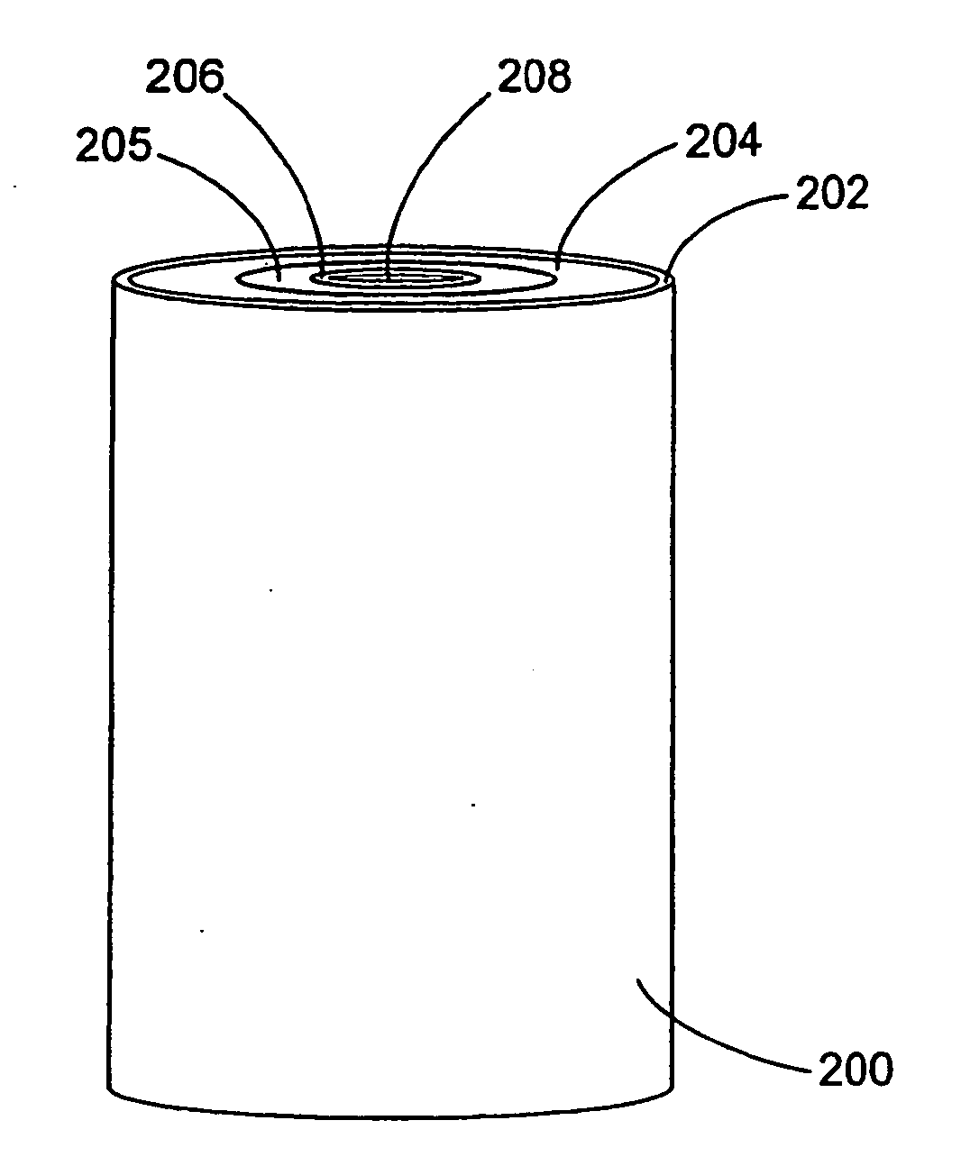
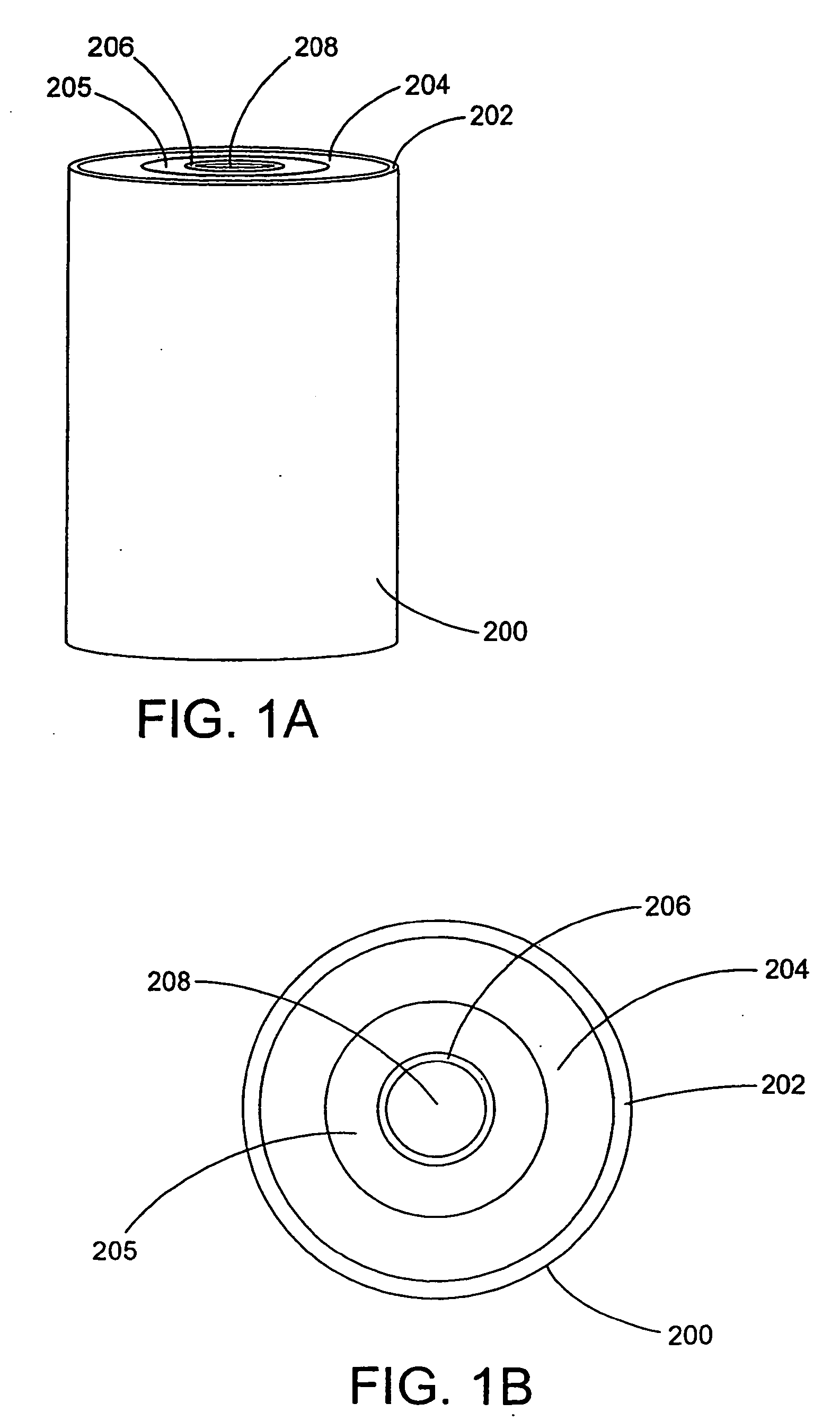
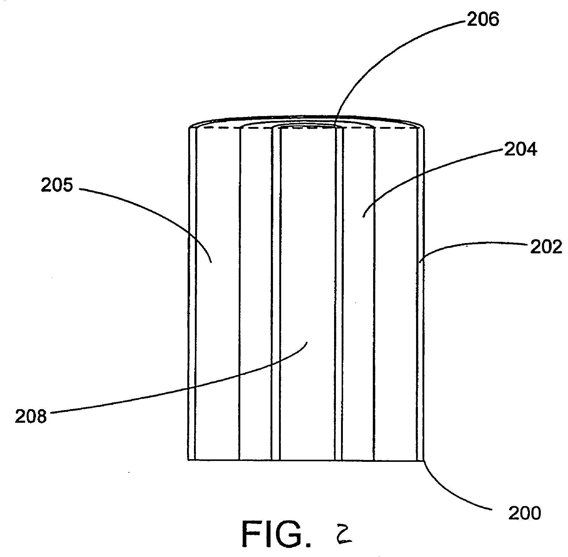
[0069]A 4.5 inch diameter shell made of porous GUR HDPE (Ticona) having a bulk density of approximately 0.85 g / cc and a micron rating of 20 to 100 micron was filled with a 80.times.325 mesh hollow core carbon produced by MeadWestVaco under the tradename AquaGuard, and vibrated for 10 min on an FMC Syntron J60 Jogger vibrating table on maximum power until compacted in the tube. The center core of the filter was a 2 inch diameter carbon fiber-containing block produced by Futumora.

[0070]The carbon block was adhered to the porous shell, and the carbon-containing media introduced and the assembly vibrated as described above. After 10 minutes, the level of particulate was the same as the level of the central core. A cap was then affixed to the top of the shell, sealing the media in the annular space between the core and the shell.

example 2

[0071]The procedures described in Example 1 were followed, except that the activated carbon particles were a mixture of 50% of 80.times.325 mesh AquaGuard carbon particles and 50% 50.times.200 mesh acid-washed coconut shell carbon.

example 3

[0072]The purification cartridge of Example 1 was tested for particulate reduction. Challenge water containing fluorescent microspheres having particle sizes in the range of 3 to 7 .mu.m in a concentration of about 67,000 per cubic centimeter was cycled through the cartridge using a duty cycle of 15 minutes on and 15 minutes off, and a flow rate of about 6.8 gpm. Water from the influent and effluent streams were sampled at the beginning of the test, and again after the indicated volume of water had been processed through the purification apparatus. The particulate levels of the samples were measured by counting in an optical microscope. The amount of particulate reduction was computed and the results are presented in Table 6 below.

TABLE 6Volume Processed(gal.)Percent ReductionStart010099.9920099.9930099.9940099.9950099.9960099.9970099.9980099.9990099.991200 99.992326 99.992687 99.993721 99.994340 99.995335 99.99

[0073]As is apparent, even with a high volumetric flow rate, the filtrat...


PUM

PropertyMeasurementUnit
Fractionaaaaaaaaaa
Fractionaaaaaaaaaa
Fractionaaaaaaaaaa

Abstract

The invention relates to a two-stage design for a water purification system, with water to be purified first passing through a first stage containing particulate filtration media, and a second stage containing a porous filtration block. The particulate filtration media can be the same as, or different from, material included in the porous block. Either material may be any material that removes contaminants from water by, e.g., absorption, adsorption, ion exchange, sequestration, or other mechanism, or any combination of these.

Description

[0001]This application is a continuation-in-part of U.S. Ser. No. 11 / 372,789, filed Mar. 10, 2006, which is a continuation-in-part of U.S. Ser. No. 10 / 723,271, filed Nov. 26, 2003, the entire contents of each of which are incorporated herein by reference.BACKGROUND OF THE INVENTION[0002]1. Field of the Invention[0003]This invention relates to apparatus and systems for efficient and effective purification of water to provide improved pressure drop characteristics and capacity as compared to purification systems using conventional carbon blocks. The apparatus and system provides substantially decreased levels of dust and fine particulates in water purified using the apparatus, when compared to conventional carbon block-based filters.[0004]2. Description of Related Art[0005]Water filtration media containing extruded or molded carbon blocks (particles of granulated activated carbon held together formed into a desired shape and held together with a polymeric binder) have been known in th...

Claims


Application Information

Patent Timeline
IPC IPC(8): B01D27/02C02F1/00
CPCB01D39/2058B01D39/2062B01D39/2065B01D2239/086B01D2239/1208C02F1/28B01D2239/1241B01D2239/125B01D2239/1291C02F1/283C02F1/288B01D2239/1233
Inventor LEVY, EHUD
Owner KINETICO
Learn More