This helps you quickly interpret patents by identifying the three key elements:
Problems solved by technology
Method used
Benefits of technology
Benefits of technology
[0009]The object of the present invention is to reduce deterioration of image quality due to low level of the table movement accuracy in the MRI apparatus or method for acquiring MR images while translating the table on which the object is placed continuously or step-wise.
Problems solved by technology
However, after reviewing the above-mentioned conventional techniques, the present inventors found the following problems.
In the above-mentioned conventional technique, in the case of imaging while translating the table continuously or step-wise and translation accuracy is low, since the image of the object is reconstructed by performing Fourier transformation etc. on the signal data obtained in the position on the object that is different from the original position meant to be imaged, the moving-table imaging method has a problem with motion artifacts being generated over the entire image, and the multi-station imaging method has a problem with a gap being generated between the adjacent stations (spatial regions which could not acquire a magnetic resonance signal) when excess amount of table translation is performed.
Method used
Image
Click on the blue label to locate the original text in one second.
Reading with bidirectional positioning of images and text.
Examples
embodiment 1
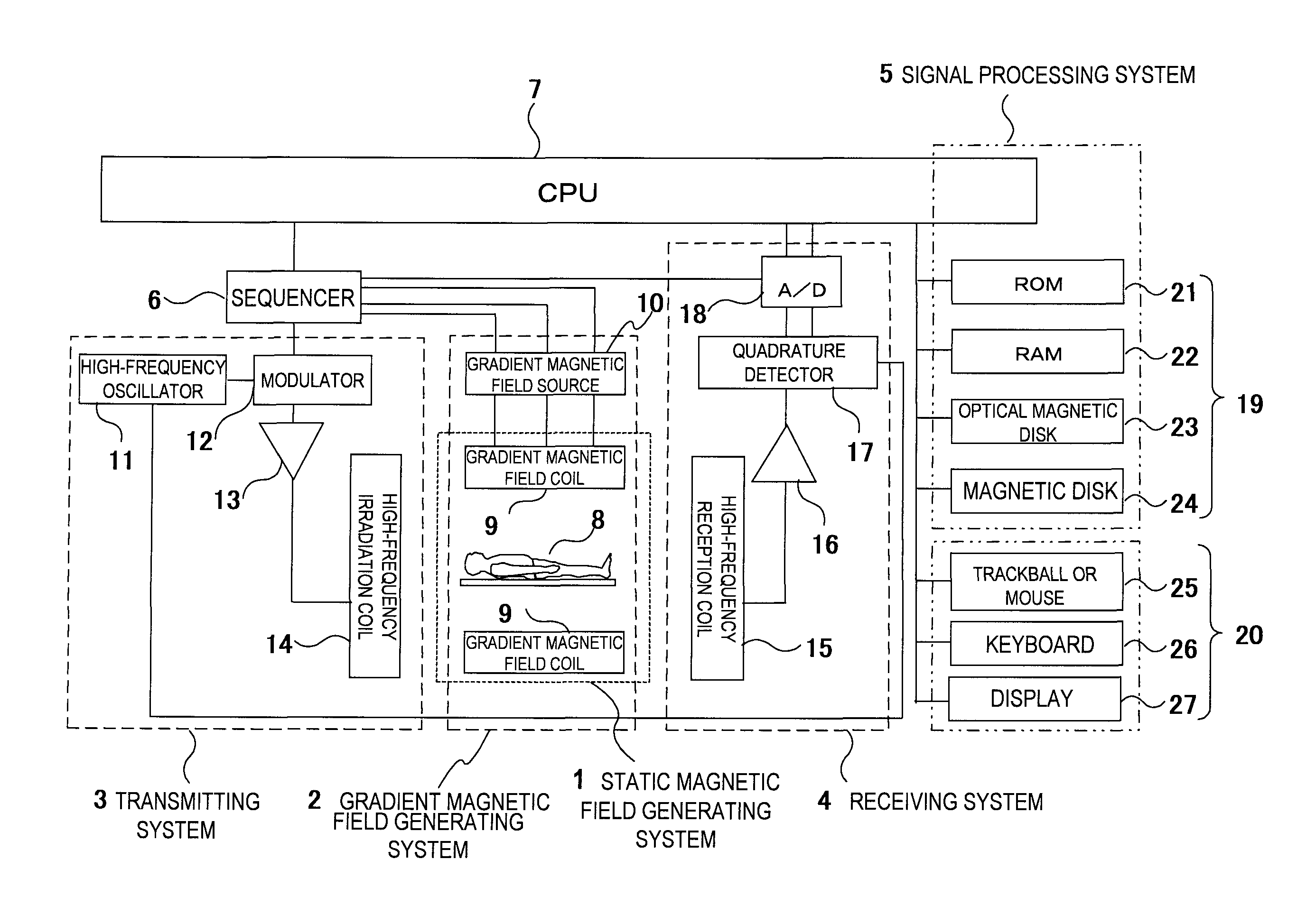
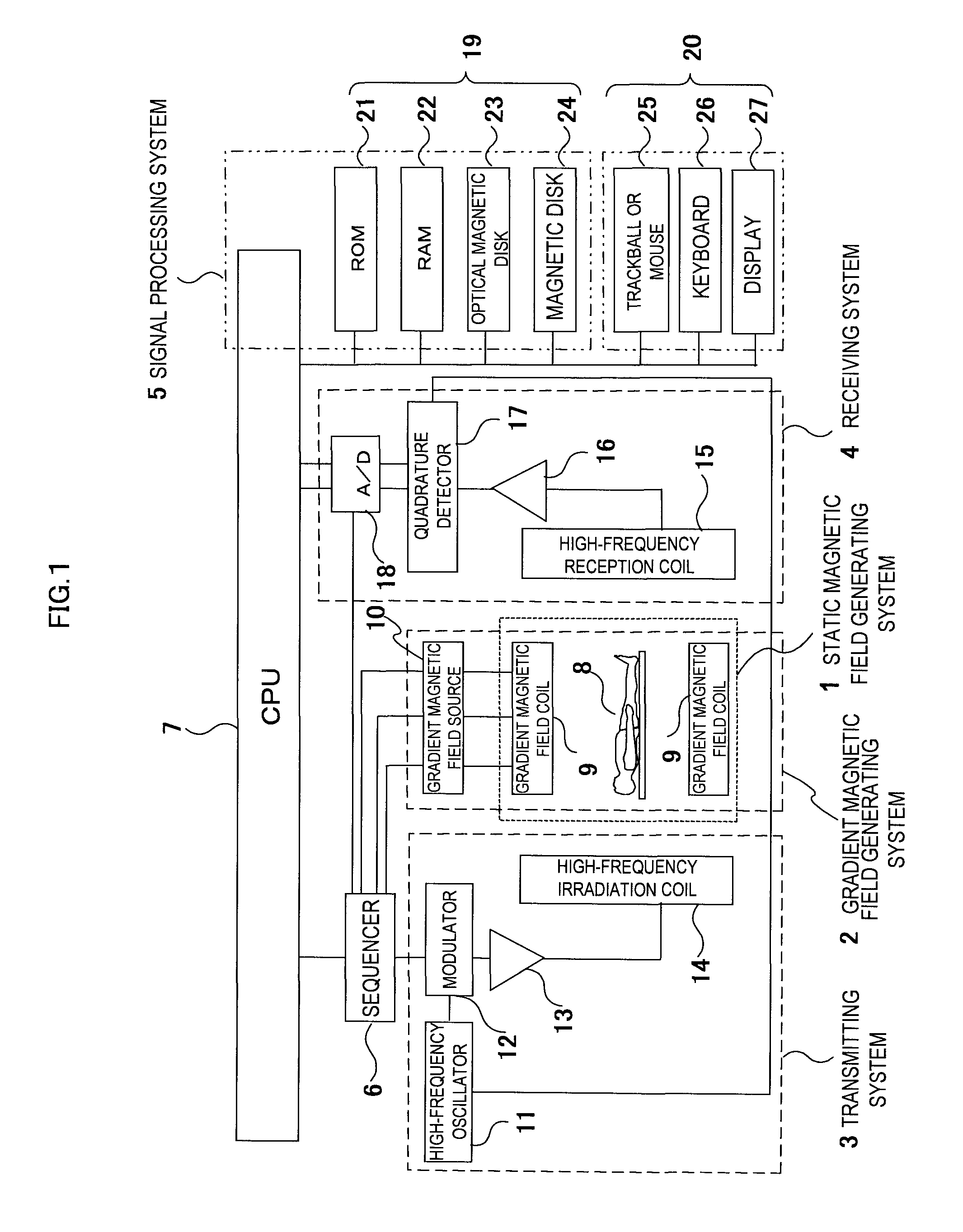
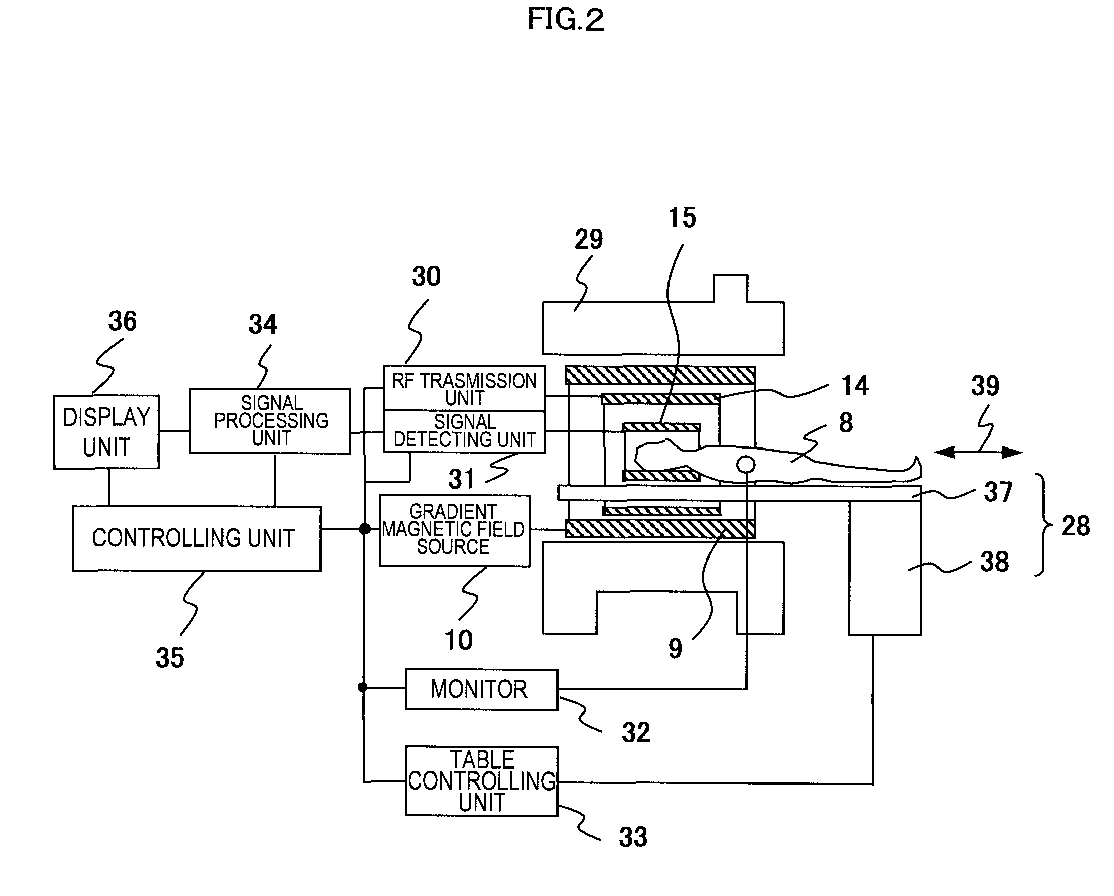
[0041]Next, the concrete configuration of the MRI apparatus in embodiment 1 will be described using FIG. 2. In FIG. 2, the MRI apparatus comprises a bed 28 on which the object 8 is placed, a magnet 29 for generating a static magnetic field around the object 8, a gradient magnetic field coil 9 for generating a gradient magnetic field in the imaging space of the static magnetic field space, a high-frequency (RF) irradiation coil 14 for generating a high-frequency magnetic, field in the imaging space, and a high-frequency reception coil (RF probe) 15 for detecting an NMR signal produced from the object 8. The MRI apparatus further comprises a gradient magnetic field source 10, an RF transmission unit 30, a signal detecting unit 31, a monitor 32, a bedcontrol unit 33, a signal processing unit 34, a control unit 35 and a display unit 36.
[0042]The gradient magnetic field coil 9 comprises a gradient magnetic field coil in X, Y and Z-directions, and generates a gradient magnetic field in a...
embodiment 2
[0067]The MRI apparatus of embodiment 2 related to the present invention will be described using FIGS. 10 (a), (b) and (c). The MRI apparatus of the embodiment 2 is configured similar as the embodiment 1 in obtaining an image of the object while recognizing the position of the table 37 by the navigator echo, but different in not using the scale fixed on the table and in using the structure of the object 8 as an index for recognizing the position.
[0068]First, FIG. 10 (a) shows the schematic view of the apparatus configuration in the present embodiment viewing from the side of the object. In accordance with FIG. 10 (a), a navigator echo acquisition region 101 is set in the inside of the object 8, and a navigator echo is obtained by the same navigator sequence as the embodiment 1. FIG. 10 (b) shows the cross-sectional image 102, and the navigator echo acquisition region 101 is placed inside of the object 8. The echo signal is A / D converted into a time-series signal by the signal detect...
embodiment 3
[0073]The MRI apparatus of the embodiment 3 related to the present invention will be described using FIGS. 11 (a)˜(c) and FIG. 12. Embodiment 3 has the same configuration as the embodiment 1 in obtaining an image of an object while monitoring the position of the table 37 by the navigator echo, but is different in that it continuously monitors the table translation position using the phase contrast (PC) method in the navigator sequence.
[0074]First, FIG. 11 (a) shows a schematic view of the apparatus configuration in the present embodiment viewing from the side of an object being laid on the table. As shown in FIG. 11 (a), the scale 111 configured by a substance that generates NMR signals is mounted on the table 37. The scale in the embodiment 3, however, has a prismatic shape homogeneous in longitudinal direction, not the comb shape as in the embodiment 1. In this embodiment, the translation distance of the table 37 is measured by obtaining the echo signal with respect to the scale 1...
PUM
Abstract
A magnetic resonance imaging apparatus comprises object placing means for placing an object in an imaging space, translating means for translating the object in a given direction by translating the object placing means in the given direction continuously or step-wise, magnetic field generating means for exciting the desired region of the object by generating a static magnetic field, a gradient magnetic field in the imaging space, and a high-frequency magnetic field in the imaging space, signal detecting means for detecting a magnetic resonancesignal from the object, and control unit for controlling the translating means, magnetic field generating means and the signal detecting means, and translating the object continuously or stepwise to a predetermined position at a predetermined speed so as to capture a magnetic resonance image of the object.The magnetic resonance imaging apparatus further comprises translation error detecting means for detecting an error of the position or the set value of the speed, and correcting means for correcting the error detected by the positional error detecting means.
Description
TECHNICAL FIELD[0001]The present invention relates to a magnetic resonance imaging apparatus (hereinafter referred to as MRI apparatus), in particular to an image quality improvement technique in a method for imaging a wide range of the region of an object to be examined while translating a table.BACKGROUND ART[0002]An MRI apparatus is for acquiring a magnetic resonance image (hereinafter referred to as an MR image) which represents the physical description of the object, when electromagnetic waves are irradiated to an object placed in a homogeneous static magnetic field, by detecting a nuclear magnetic resonance signal (hereinafter referred to as NMR signal) from the object using nuclear magnetic resonance (hereinafter referred to as NMR) phenomenon being generated in atomic nuclei of atomy by which the object is formed, and constructing an image using the NMR signals.[0003]In MRI, a technique is known for imaging a wide range or a whole body of an object while translating a table ...
Claims
Application Information
Patent Timeline
Application Date:The date an application was filed.
Publication Date:The date a patent or application was officially published.
First Publication Date:The earliest publication date of a patent with the same application number.
Issue Date:Publication date of the patent grant document.
PCT Entry Date:The Entry date of PCT National Phase.
Estimated Expiry Date:The statutory expiry date of a patent right according to the Patent Law, and it is the longest term of protection that the patent right can achieve without the termination of the patent right due to other reasons(Term extension factor has been taken into account ).
Invalid Date:Actual expiry date is based on effective date or publication date of legal transaction data of invalid patent.

