

Method of producing optical laminate and image displaying apparatus
a technology of optical laminate and image displaying apparatus, which is applied in the direction of liquid surface applicators, instruments, coatings, etc., can solve the problems of long drying time for drying wet applied film, inferior optical characteristics of applied film thus becoming white turbidity, and white turbidity generation
- Summary
- Abstract
- Description
- Claims
- Application Information
AI Technical Summary
Benefits of technology
Problems solved by technology
Method used
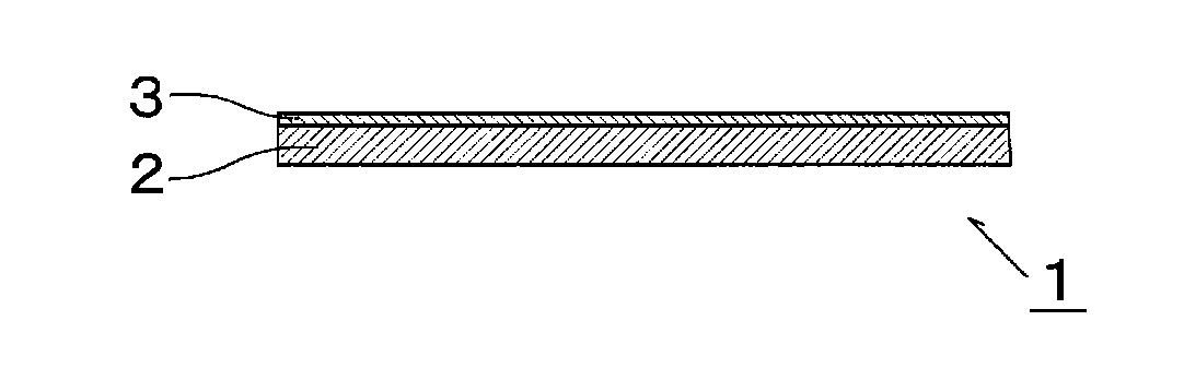
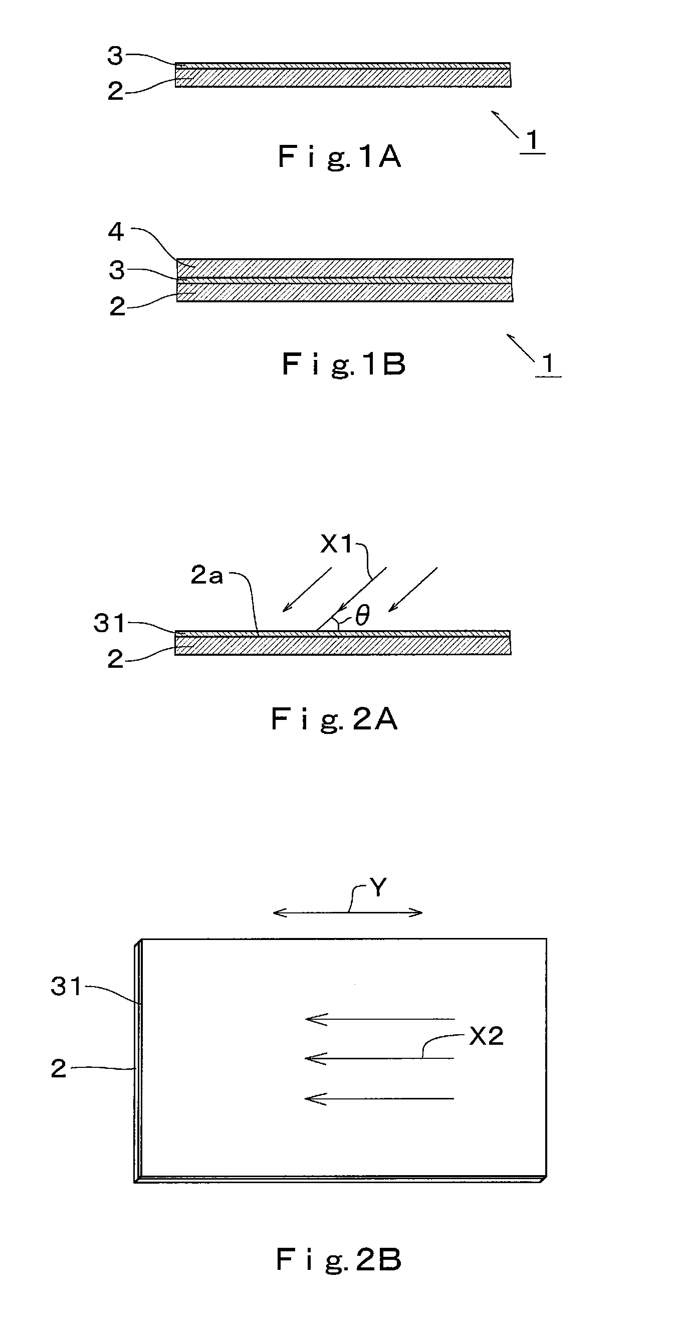
Image

Examples
synthesis example 1
Synthesis of acenaphtho[1,2-b]quinoxaline
[0121]To a reaction vessel equipped with a stirrer, 5-liter of glacial acetic acid and 490 g of purified acenaphthenequinone were added and stirred for 15 minutes under nitrogen bubbling to obtain an acenathphenequinone solution. Similarly, to another reaction vessel equipped with a stirrer, 7.5-liter of glacial acetic acid and 275 g of o-phenylenediamine were added and stirred for 15 minutes under nitrogen bubbling to obtain an o-phenylenediamine solution. Thereafter, while stirring under nitrogen atmosphere, the o-phenylenediamine solution was added to the acenaphthenequinone solution gradually over one hour, and then allowed to react by continuing to stir for 3 hours. After ion exchange water was added to the obtained reaction liquid, the precipitate was filtrated to obtain a crude product. This crude product was recrystallized with a heated glacial acetic acid for purification.
synthesis example 2
Synthesis of acenaphtho[1,2-b]quinoxaline-2,5-disulfonic Acid
[0122]As represented by the following reaction pathway, after 30% fuming sulfuric acid (2.1-liter) was added to 300 g of acenaphtho[1,2-b]quinoxaline obtained by synthesis example 1 and the mixture was stirred at room temperature for 24 hours, the resultant was heated to 130° C. and stirred for 32 hours for reaction. While keeping the obtained solution at 40° C. to 50° C., 4.5-liter of ion exchange water was added for dilution, and the resultant was further stirred for 3 hours. The precipitate was filtered and recrystallized with sulfuric acid to obtain acenaphtho[1,2-b]quinoxaline-2,5-disulfonic acid as represented by the following formula (c).
[0123]This reaction product was dissolved in 30-liter of ion exchange water (electric conductivity: 0.1 μS / cm) and further was neutralized by addition of an aqueous solution of sodium hydroxide. The obtained aqueous solution was put into a supply tank and, with use of a high-pressur...
synthesis example 3
Synthesis of acenaphtho[1,2-b]quinoxaline-2-sulfonic Acid
[0124]As represented by the following reaction pathway, 30% fuming sulfuric acid (2.1-liter) was added to 300 g of acenaphtho[1,2-b]quinoxaline obtained by synthesis example 1 and the mixture was stirred at room temperature for 48 hours for reaction. While keeping the obtained solution at 40° C. to 50° C., 4.5-liter of ion exchange water was added for dilution, and the resultant was further stirred for 3 hours. The precipitate was filtered to obtain acenaphtho[1,2-b]quinoxaline-2-sulfonic acid as represented by the following formula (d).
[0125]This reaction product was dissolved in 30-liter of ion exchange water (electric conductivity: 0.1 μS / cm) and further was neutralized by addition of an aqueous solution of sodium hydroxide. The obtained aqueous solution was put into a supply tank and, with use of a high-pressure RO element testing apparatus equipped with a reverse osmosis filter manufactured by Nitto Denko Corporation [tra...
PUM
| Property | Measurement | Unit |
|---|---|---|
| thickness | aaaaa | aaaaa |
| temperature | aaaaa | aaaaa |
| transparency | aaaaa | aaaaa |
Abstract
Description
Claims
Application Information