Sterilization/Aseptization Apparatus

a technology of sterilization and aseptization, which is applied in the direction of water installations, disinfection, construction, etc., can solve the problems of large energy consumption of sterilization, and the large scale of the apparatus used for sterilization and aseptization

Inactive Publication Date: 2010-09-02
NGK INSULATORS LTD
View PDF15 Cites 15 Cited by
  • Summary
  • Abstract
  • Description
  • Claims
  • Application Information

AI Technical Summary

Benefits of technology

[0010]With this feature, in addition to that cell membrane of bacteria is destroyed by the pulse electric field and DNA of bacteria is destroyed by the nitrogen radical, short-wavelength ultraviolet ray having high bactericidal effect can be caused to act effectively on bacteria, and therefore, sterilization or aseptization can be carried out with a small amount of energy.
[0050]This allows manufacturing of plate-shape members in short time at inexpensive costs.

Problems solved by technology

However, electron beam irradiation method, heating method, and ultraviolet ray method have such problems that a large quantity of energy is consumed for sterilization or aseptization, and apparatuses used for sterilization and aseptization tend to become large-scaled.

Method used


Image

  • Sterilization/Aseptization Apparatus
  • Sterilization/Aseptization Apparatus
  • Sterilization/Aseptization Apparatus

Examples


first embodiment

2.1 First Embodiment

2.1.1 Configuration of Aseptization Apparatus

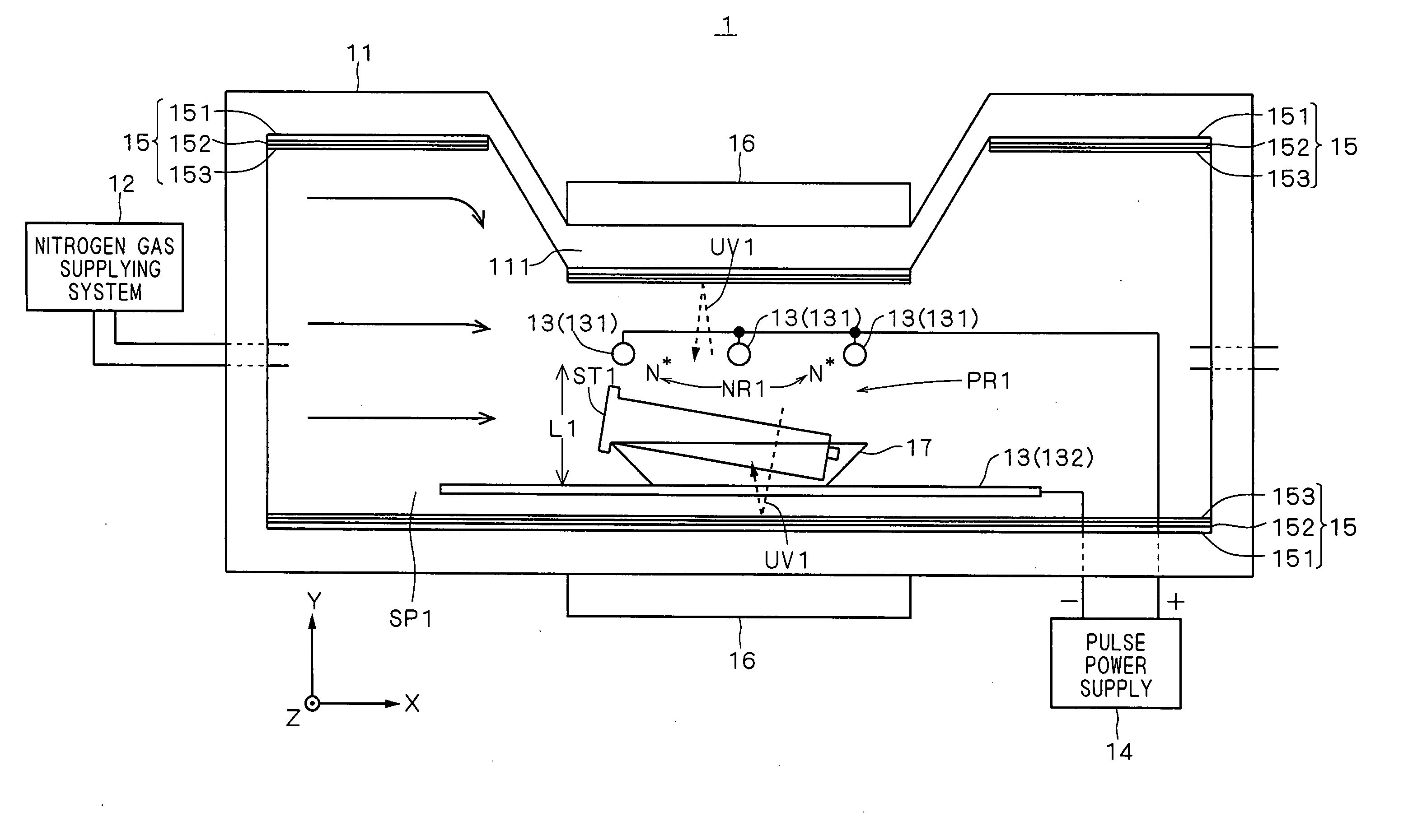
[0112]FIG. 6 is a cross-sectional view schematically showing an example of the configuration of the aseptization apparatus 1 according to a first embodiment of the present invention. The aseptization apparatus 1 is configured for aseptization of the surface of aseptization object substance ST1 having steric profile such as syringe. In FIG. 6, for convenience of explanation, X-Y-Z orthogonal coordinate system is defined in which right and left directions are X-axis direction, up and down directions are Y-axis direction, and fore and aft directions are Z-axis direction.

[0113]As shown in FIG. 6, the aseptization apparatus 1 includes a hollow sealed container 11 for forming a space (also referred hereinafter to as “aseptization space”) SP1 where aseptization is carried out, a nitrogen gas supplying system 12 which converts atmosphere of the aseptization space SP1 to nitrogen atmosphere, an electrode pair 13 disposed in the...

second embodiment

2.2 Second Embodiment

2.2.1 Configuration of Aseptization Apparatus

[0154]FIG. 11 is a cross-sectional view showing the configuration of the aseptization apparatus 2 according to the second embodiment of the present invention. The aseptization apparatus 2 is configured in such that the surface of an aseptization object substance ST2 having planar shape such as film is aseptized. In FIG. 11, for convenience of explanation, X-Y-Z orthogonal coordinate system is defined in which right and left directions are X-axis direction, up and down directions are Y-axis direction, and fore and aft directions are Z-axis direction.

[0155]As shown in FIG. 11, the aseptization apparatus 2 includes a hollow sealed container 21 for forming an aseptization space SP2, a nitrogen gas supplying system 22 which converts atmosphere of the aseptization space SP2 to nitrogen atmosphere, an electrode pair 23 disposed in the aseptization space SP2, a pulse power supply 24 for repeatedly applying an electric pulse t...

third embodiment

2.3 Third Embodiment

2.3.1 Configuration of Aseptization Apparatus

[0162]FIG. 13 is a perspective view showing whole configuration of an aseptization apparatus 3 according to a third embodiment of the present invention. In FIG. 13, for convenience of explanation, X-Y-Z orthogonal coordinate system is defined in which fore and aft directions (depth direction) are X-axis direction, right and left directions (width direction) are Y-axis direction, and up and down directions (height direction) are Z-axis direction.

[0163]The aseptization apparatus 3 shown in FIG. 13 is designed to kill bacteria adhered on a sheet ST3 used as the packing materials for medical devices and food articles, and to destroy DNA and toxin held by the bacteria. Although materials of the sheet ST3 which can be an aseptization object substance of the aseptization apparatus 3 are not specifically limited, for example, plastic resin such as polyethylene, Teflon (registered trademark), polyvinyl chloride, and polyethylen...


PUM


Abstract

An aseptization apparatus 1 includes a sealed container 11 forming an aseptization space 191, a nitrogen gas supplying system 12 for converting atmosphere of the aseptization space 191 into nitrogen atmosphere, an electrode pair 13 disposed in the aseptization space 191, a pulse power supply 14 for repeatedly applying an electric pulse to the electrode pair 13, and a mirror 15 for returning a short-wavelength ultraviolet ray going from inside of the aseptization space 191 to outside to inside of the aseptization space 191. In a state where an aseptization object substance ST1 is present in a plasma generation region 192 between the electrode pair 13, the aseptization apparatus 1 causes a pulse electric field generated by electric pulse application to the electrode pair 13, a nitrogen radical 195 contained in plasma generated in nitrogen atmosphere resulting from fine streamer discharge, and a short-wavelength ultraviolet ray 196 emitted by nitrogen atmosphere resulting from fine streamer discharge to act on bacteria for aseptization of the aseptization object substance ST1.

Description

TECHNICAL FIELD[0001]The present invention relates to a sterilization / aseptization apparatus for sterilizing or aseptizing a target substance.BACKGROUND ART[0002]Conventionally, ethylene oxide gas method, hydrogen peroxide gas plasma method, gamma-ray irradiation method, electron beam irradiation method, heating method, ultraviolet ray method, and the like have been used for sterilization and aseptization purposes.[0003]Among afore-mentioned methods, ethylene oxide gas method has such a problem that ethylene oxide gas used for sterilization and aseptization has toxic consequences. In addition, ethylene oxide gas is suspected for its carcinogenicity, and it is predicted that regulations imposed on ethylene oxide gas will become stricter in the future.[0004]In the meantime, with hydrogen peroxide gas plasma method, which has higher safety than ethylene oxide gas method, there is a restriction that application to such a case where a steric substance to be subjected to sterilization and...

Claims


Application Information

Patent Timeline
Patent Type & Authority Applications(United States)
IPC IPC(8): A61L2/02B01J19/12A61L2/10A61L2/14
CPCA61L2/14A61L2/10
Inventor SHIMIZU, NAOHIROWAKITA, MASAHIROIMANISHI, YUICHIRO
Owner NGK INSULATORS LTD
Why Eureka
Try Eureka