
Apparatus for production of fiber-reinforced resin strand

a technology of fiber-reinforced resin and manufacturing apparatus, which is applied in the direction of surface layering apparatus, manufacturing tools, coatings, etc., can solve the problem of high production rate of fiber-reinforced resin strand, and achieve the effect of high production ra

Active Publication Date: 2010-09-09
KOBE STEEL LTD
View PDF15 Cites 18 Cited by
  • Summary
  • Abstract
  • Description
  • Claims
  • Application Information

AI Technical Summary

Benefits of technology

[0008]An object of the invention is to provide a manufacturing apparatus of a fiber-reinforced resin strand capable of manufacturing a fiber-reinforced resin strand at a high production rate.
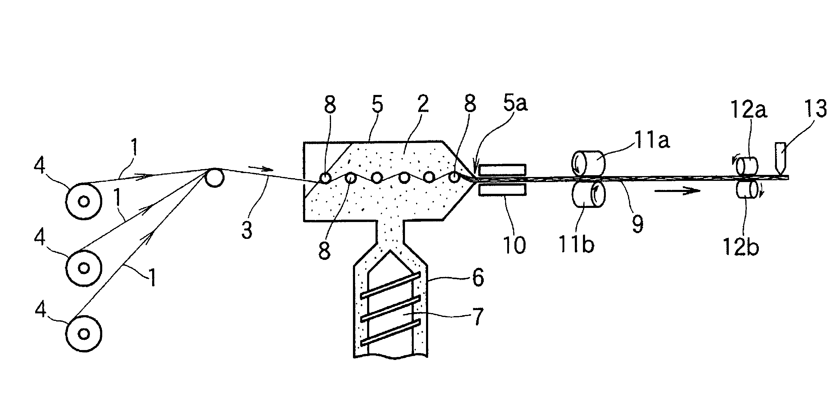
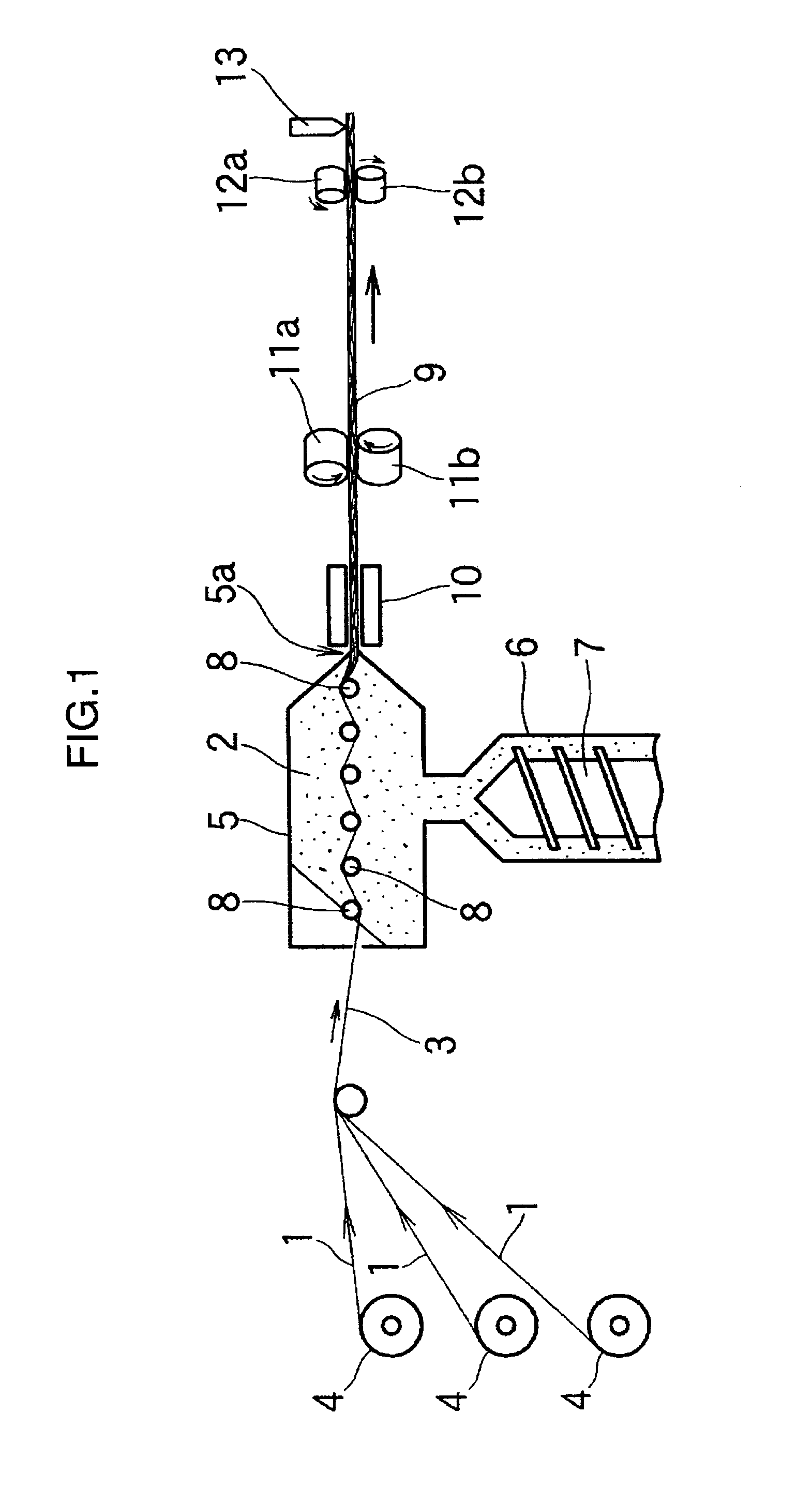
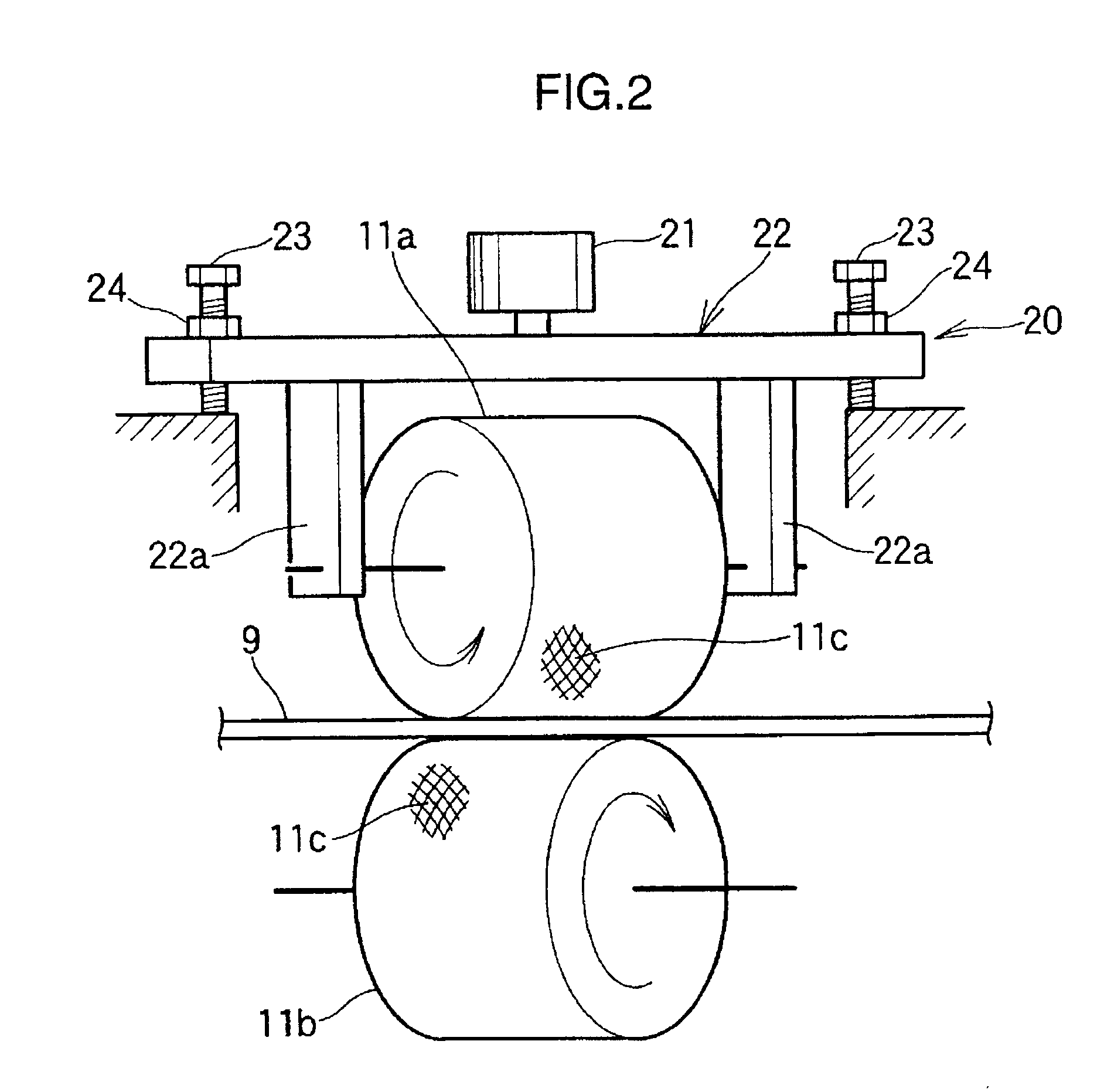
[0010]With the manufacturing apparatus of a fiber-reinforced resin strand according to claim 1 of the invention, for at least a pair of rollers that pultrudes a fiber-reinforced resin strand formed of a resin-impregnated fiber bundle from the exit nozzle of the crosshead while twisting the fiber-reinforced resin strand, each roller is made of metal on the surface of which the asperities are formed. Hence, because a frictional coefficient between the both rollers and the fiber-reinforced resin strand increases owing to the asperities on the twisting rollers, it is possible to suppress the occurrence of slipping when the fiber-reinforced resin strand is pultruded. In addition, because the twisting rollers are made of metal, they are more resistant to wear and have a longer life than twisting rollers made of rubber in the first prior art. It is thus possible to keep pultruding the fiber-reinforced resin strand over a long period.
[0013]Hence, even when the pultruding rate of the reinforcing fiber bundle is accelerated, not only is it possible to let the reinforcing fiber bundle be impregnated with molten resin sufficiently owing to the ability to suppress a temperature drop of the molten resin inside the crosshead, but it is also possible to suppress an increase in tension of the reinforcing fiber bundle (resin-impregnated reinforcing fiber bundle) that travels through the crosshead owing to the ability to suppress an increase in viscosity of the molten resin inside the crosshead. Hence, not only can a fiber-reinforced resin strand be manufactured at a pultruding rate higher than the conventional pultruding rate (production rate), for example, a pultruding rate exceeding 40 m / min, but also an installment space for the heating roller device provided to accelerate the pultruding rate can be smaller.
[0015]The manufacturing apparatus of a fiber-reinforced resin strand according to Claim 12 includes the cooling device provided between the crosshead and the twisting rollers. Plural water ejection nozzles are provided in the cooling water bath storing cooling water for the hot fiber-reinforced resin strand pultruded from the crosshead to pass through while being spaced apart in the traveling direction of the fiber-reinforced resin strand for ejecting water toward the fiber-reinforced resin strand in the cooling water. Hence, by stirring the cooling water inside the cooling water bath with a water flow developed by ejection of water from the water ejection nozzles, a fresh cooling water flow is continuously introduced to come into contact with the fiber-reinforced resin strand that passes through the cooling water. It is thus possible to accelerate the cooling rate for the fiber-reinforced resin strand by efficiently performing heat exchange between the fiber-reinforced resin strand and the cooling water in comparison with a cooling water bath equipped with no water ejection nozzles. Accordingly, in a case where a fiber-reinforced resin strand is manufactured at a high pultruding rate, for example, a pultruding rate exceeding 40 m / min, it is possible to cool the fiber-reinforced resin strand sufficiently without the need to extend the length of the cooling water bath (the length in the fiber-reinforced resin strand traveling direction) in comparison with the case of the conventional pultruding rate of 40 m / min or lower. It is thus possible to manufacture a fiber-reinforced resin strand formed of a reinforcing fiber bundle sufficiently impregnated with the resin material at a higher pultruding rate than the conventional pultruding rate, for example, a pultruding rate exceeding 40 m / min, without causing slipping of the continuous fiber-reinforced resin strand in the twisting device.

Problems solved by technology

However, the manufacturing apparatus of a fiber-reinforced resin strand according to Patent Document 1 has a problem that it is difficult to manufacture a fiber-reinforced resin strand at a high production rate (for example, 40 m / min).Patent Document 1: JP-A-5-169445

Method used


Image

  • Apparatus for production of fiber-reinforced resin strand
  • Apparatus for production of fiber-reinforced resin strand
  • Apparatus for production of fiber-reinforced resin strand

Examples


example

[0161]A manufacturing test of a fiber-reinforced resin strand was conducted using the apparatus shown in FIG. 15 and FIGS. 10 through 12. A glass fiber was used as a reinforcing fiber and polypropylene was used as thermoplastic resin.

[0162]The cooling device 27 in Examples 1 through 4 will now be described. The length of the cooling water bath 28 was 2 m. Regarding the water ejection nozzles 29, 20 of them were disposed in a line on one side (the lower side of FIG. 10) and 20 of them were disposed in a line on the other side (the upper side of FIG. 10) with respect to the strand traveling path in a stagger fashion with the fiber-reinforced resin strand traveling path in between. The distance between the center lines of the adjacent water ejection nozzles 29 in the strand traveling direction was 70 mm. The length of the cooling water bath 28 in Comparative Example 1 and Comparative Example 2 was also 2 m (in Comparative Examples 1 and 2, no water ejection nozzles 29 were provided).

[0...


PUM

PropertyMeasurementUnit
Diameteraaaaaaaaaa
Forceaaaaaaaaaa
Angleaaaaaaaaaa

Abstract

A manufacturing apparatus of a fiber-reinforced resin strand including spreaders that spread a reinforcing fiber bundle and are provided inside a crosshead to which a molten resin material is supplied continuously from an extruding machine, twisting rollers provided at a downstream position from an exit nozzle of the crosshead and that pultrude a fiber-reinforced resin strand formed of a resin-impregnated fiber bundle from the exit nozzle while imparting twists thereto, and twist retaining rollers provided at a downstream position from the twisting rollers and that retain twists of the fiber-reinforced resin strand. The twisting rollers and the twist retaining rollers are made of metal with asperities being formed on the surface thereof. The manufacturing apparatus can achieve excellent durability and is capable of manufacturing a fiber-reinforced resin strand at a high production rate without causing slipping.

Description

TECHNICAL FIELD[0001]The present invention relates to a manufacturing apparatus of a fiber-reinforced resin strand, and more particularly, to a manufacturing apparatus of a fiber-reinforced resin strand achieving excellent productivity of a fiber-reinforced resin strand.BACKGROUND ART[0002]Pellets made by cutting a long fiber-reinforced resin strand into pieces, for example, of about 3 to 15 mm in length are used in the manufacture of injection molded articles, such as vehicle interior members (the console box, the instrument panel, etc.), vehicle exterior members (the bumper, the fender, etc.), and the housing for electronic device members (a notebook personal computer, a mobile phone, etc.).[0003]As techniques according to a prior art relating to a fiber-reinforced resin strand and a manufacturing apparatus thereof, for example, configurations described below are known. To begin with, a manufacturing apparatus of a fiber-reinforced resin strand according to a first prior art will ...

Claims


Application Information

Patent Timeline
IPC IPC(8): B32B38/08B32B37/02B32B37/06B32B37/08B32B37/24
CPCB29B9/14B29C70/504B29C70/20B29B15/122B29K2105/12B29C48/05B29C48/345B29C48/156B29C48/04B29C48/0022B29B9/06
Inventor TASHIRO, NAOYUKIYAMAMOTO, ATSUSHIFUKUTANI, KAZUHISAMATSUBARA, YOSHIAKIOGAWA, KATSUMI
Owner KOBE STEEL LTD
Learn More