Ferrous Sintered Multilayer Roll-Formed Bushing, Producing Method of the Same and Connecting Device
- Summary
- Abstract
- Description
- Claims
- Application Information
AI Technical Summary
Benefits of technology
Problems solved by technology
Method used
Image
Examples
example 1
(Experiment for Preliminary Sintering Ability of Various Ferrous Sintered Sliding Materials)
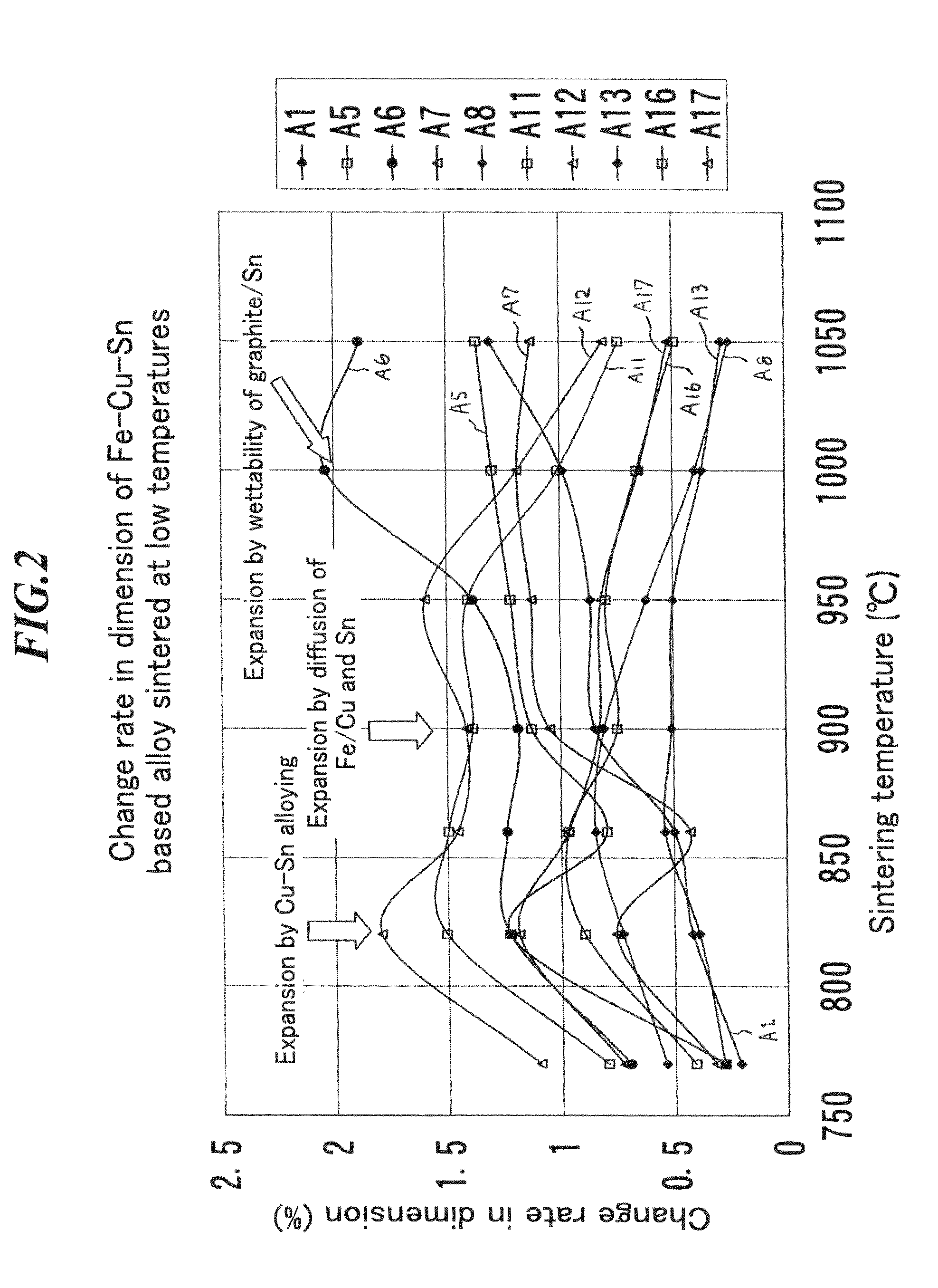
[0295]Three kinds of Cu alloy mixed powders shown in Table 1 were prepared. Ferrous sintered alloys having compositions shown in Table 3 were used in the embodiment. These sintered alloys were prepared in composition by using A300 (iron powder, manufactured by Kobe Steel, Ltd.), PX16 (high-speed steel powder Fe-1.1 wt % C-4 wt % Cr-5 wt % Mo-6 wt % W-2 wt % V, manufactured by Mitsubishi Steel Mfg. Co., Ltd.), KM15 (high Cr tool steel powder, Fe-0.45 wt % C-16 wt % Cr-3 wt % Mo-2 wt % V, manufactured by Mitsubishi Steel Mfg. Co., Ltd.), atomized copper powder of −#350 mesh or less (manufactured by FUKUDA METAL FOIL & POWDER CO., LTD.), atomized Cu-33 wt % Sn powder (manufactured by FUKUDA METAL FOIL & POWDER CO., LTD.), atomized Sn powder of −#250 mesh or less (manufactured by FUKUDA METAL FOIL & POWDER CO., LTD.) and graphite having an average grain size of 6 μm (KS6, manufactured by LONZA). ...
example 2
(Experiment for Final Sintering Ability of Various Ferrous Sintered Sliding Materials)
[0313]Tables 3-1 and 3-2 show compositions of mixed powders for ferrous sintered sliding material alloys used in the example.
[0314]Theses sliding material were prepared were prepared in composition by using ASC300 (iron powder, manufactured by Hoganas), M2 (high-speed steel powder, Fe-0.8 wt % C-4 wt % Cr-5 wt % Mo-6 wt % W-2 wt % V, manufactured by Mitsubishi Steel Mfg. Co., Ltd.), SUS440C (Fe-1.1 wt % C-17 wt % Cr, manufactured by NIPPPON ATOMIZED METAL POWDER CORRPORATION), electrolytic copper powder (CE25, manufactured by FUKUDA METAL FOIL & POWDER Co., Ltd.), TiH of −#350 mesh or smaller, electrolytic Mn, Ni, phosphor iron (25 wt % P), Mo having an average grain size of 5 μm, Fe-16 wt % Al-25 wt % Cu of #200 mesh or smaller and Fe-16 wt % Al, in addition to the powders used in Example 1. These mixed powders were formed into the test piece at a pressure of 5 ton / cm2. Each test piece was vacuum ...
example 3
(Method for Producing a Ferrous Sintered Roll-Formed Bushing 1)
[0355]Table 4 shows compositions of alloys of ferrous sintered sliding materials used in the Example.
[0356]These sliding materials were prepared in composition by using raw material powders used in Examples 1 and 2. Each mixed powder was dispersed on a SPCC steel plate 4 mm in thickness to have a thickness of 1.4 mm. Then, after preliminary sintering at 900° C. for 15 minutes, the about 50% sintered layer was reduced by a reduction machine and then preliminarily sintered again at 900° C. for 15 minutes. After cooling, it was finally sintered at various temperatures within 1000 to 1200° C. for 30 minutes. Then, it was rapidly cooled using N2 gas of 600 torr from the sintering temperatures. The sintered body was observed and examined in sintering ability of the alloys and a lower limit of sintering temperature at which a sufficient bonding strength between each alloy and the back metal steel can be obtained.
[0357]FIGS. 18A...
PUM
| Property | Measurement | Unit |
|---|---|---|
| Grain size | aaaaa | aaaaa |
| Grain size | aaaaa | aaaaa |
| Grain size | aaaaa | aaaaa |
Abstract
Description
Claims
Application Information
 - R&D
- Intellectual Property
- Life Sciences
- Materials
- Tech Scout
- Unparalleled Data Quality
- Higher Quality Content
- 60% Fewer Hallucinations
Browse by: Latest US Patents, China's latest patents, Technical Efficacy Thesaurus, Application Domain, Technology Topic, Popular Technical Reports.
© 2025 PatSnap. All rights reserved.Legal|Privacy policy|Modern Slavery Act Transparency Statement|Sitemap|About US| Contact US: help@patsnap.com


