System and method for remotely monitoring and controlling pump jacks

a pump jack and remote monitoring technology, applied in the field of remote monitoring systems and methods, can solve the problems of difficult obstruction of the remote location of the pump jack, inability to monitor (and/or control) in the prior art, and large bandwidth requirements, and achieve the effect of simple and effective remote monitoring and control

Inactive Publication Date: 2010-09-09
RIEMER POWERS CORP
View PDF20 Cites 28 Cited by
  • Summary
  • Abstract
  • Description
  • Claims
  • Application Information

AI Technical Summary

Benefits of technology

[0016]Accordingly, as a means of overcoming the shortcomings of the prior art with respect to monitoring and control of remotely-situated pumpjacks, the present invention allows for simple and effective remote monitoring and control of pumpjacks in remote locations in which access to the internet (world-wide web) is not (or is not readily) available at such remote locations, but where cellular telephone wireless coverage is available.

Problems solved by technology

In numerous remote locations, however, internet access which may be by telephone cable (ASDL) connection, co-axial cable, or digital satellite (which is typically only “line of sight” to a transmitter tower) may not be available, and accordingly such means of monitoring (and / or control) in the prior art is not possible.
Such data format, however, typically requires large bandwidth which in turn requires local access to the internet (ie an internet gateway) at the remote location in order to handle such large bandwidth requirements.
Problematically, while some hydrocarbon formations and associated pumpjacks may fortuitously be situated proximate to an electric utility grid and relatively close to industrial metropolitan conveniences such as internet gateway access, frequently pumpjacks are located in remote locations and need be powered by self-contained internal combustion motors.
The remote location of the pumpjacks is a difficult obstacit in the effort to continuously monitor such pumpjacks for efficient and continuous operation.

Method used


Image

  • System and method for remotely monitoring and controlling pump jacks
  • System and method for remotely monitoring and controlling pump jacks
  • System and method for remotely monitoring and controlling pump jacks

Examples


Embodiment Construction

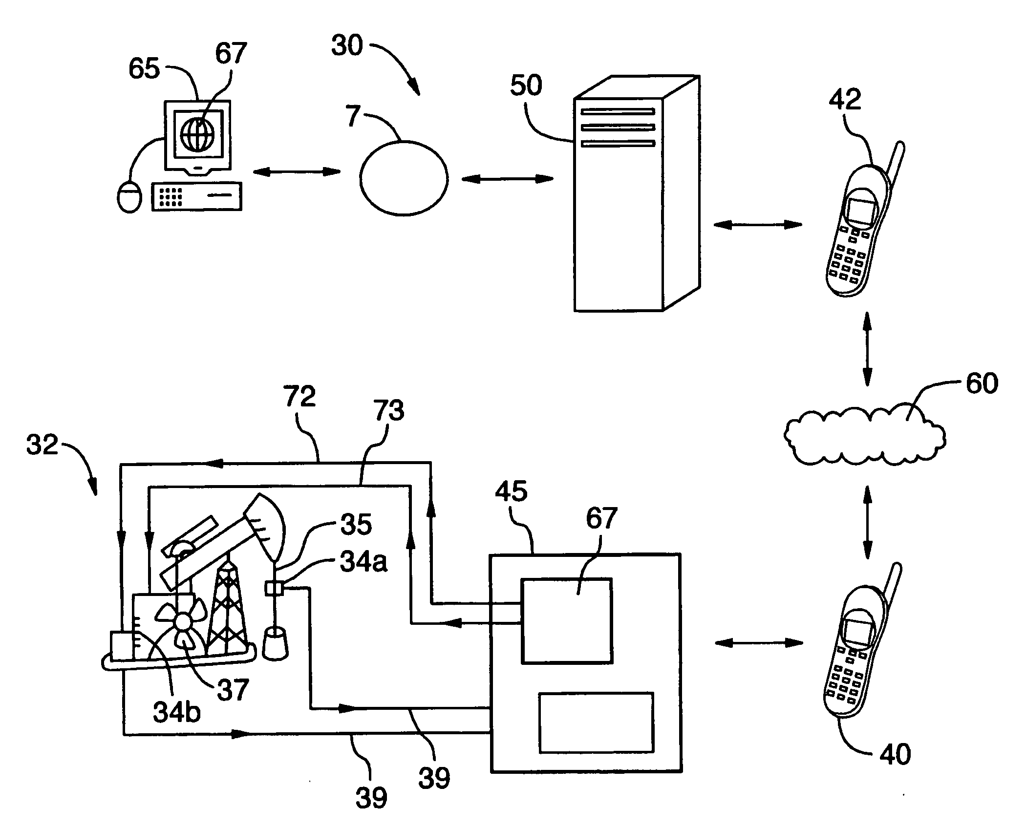
[0056]FIG. 4 schematically illustrates a preferred system 30 and method of the present invention.

[0057]Specifically, as seen from FIG. 4, the system 30 comprises a pumpjack 32, remotely situated, but in a region of cellular telephone transmission, having a plurality of monitoring sensors 34a, 34b thereon. In the embodiment shown in FIG. 4, sensor 34a is a load cell sensor, effectively a strain gauge, located on the polish rod 35 of pumpjack 32, which provides an electrical output [which output is typically analog and is digitized to a digital output by digitizing means (not shown) internal to the load cell sensor 34a or external to load cell sensor 34a], and which provides digital values for the force applied to polish rod 35 of the pumpjack 32.

[0058]Sensor 34b is a speed sensor, which provides, via digitizing means (not shown) a digital output of the speed of the motor 37 of pumpjack 32.

[0059]Other similar sensors (not shown), together with sensors 34a, 34b, may be provided on pump...


PUM


Abstract

A simplified system and method for remotely monitoring and optionally further controlling pumpjack operating parameters of a pumpjack located at a distant site but within wireless cell phone station reception. Sensors situated on a pumpjack monitor and create analog output of operational conditions of the pumpjack. Digitizing means digitize the analog output of the sensors to digital data, and modem means transmit the digital data via a wireless cellular network to a network server. A user's computer communicates with the network server via the internet, and accesses the digital data to obtain information regarding the operational conditions of the pumpjack.

Description

FIELD OF THE INVENTION[0001]This invention relates to a system and method for remotely monitoring, and further optionally controlling, pumpjacks.BACKGROUND OF THE INVENTION AND DESCRIPTION OF THE PRIOR ART[0002]Systems and methods for remotely controlling equipment over the internet are known.[0003]For example, FIG. 1 hereto shows a known method / system of the prior art for remotely controlling an electric motor 2. A web relay device 3 possesses at least one relay switch (not shown) which when actuated is used to turn “on” and “off” electrical power supply 4 to various operating systems on a device such as the large electrical motor 2 shown. Of course, while only electrical power supply 4 to a large electrical motor 2 is shown as being controlled, existing web relays 3 typically have a plurality of “on” / “off” relays which may be used to control other electrically actuated devices and subsystems, such as other larger solenoids or electrically operated valves which control the flow of ...

Claims


Application Information

Patent Timeline
Patent Type & Authority Applications(United States)
IPC IPC(8): G05D7/00G06F15/00
CPCF04B49/065F04B2201/0204F04B2201/0206F04B2201/0207H04L67/12F04B2201/1211H04L67/08H04L67/025F04B2201/121
Inventor POWERS, JAMESRIEMER, CAL
Owner RIEMER POWERS CORP
Why Eureka
Try Eureka