Gas turbine combustor

a combustor and gas turbine technology, applied in mechanical equipment, machines/engines, lighting and heating equipment, etc., can solve the problems of man-hours, increasing the number of components, and reducing the efficiency of the apparatus, so as to reduce the unevenness of the fuel concentration, the mixing effect between compressed air and the fuel is highly enhanced, and the fuel concentration is less uneven

Active Publication Date: 2010-09-16
KAWASAKI HEAVY IND LTD
View PDF15 Cites 74 Cited by
  • Summary
  • Abstract
  • Description
  • Claims
  • Application Information

AI Technical Summary

Benefits of technology

[0026]In this configuration, the inflow adjuster can positively suppress unwanted variation, in the circumferential direction, of the dynamic pressure of the compressed air flowed into the inlet port. As such, the amount of the compressed air flowed into the introducing passage from the inlet port can be controlled to be more uniform in the circumferential direction. Therefore, the pre-mixed gas that can exhibit significantly less unevenness of the fuel concentration can be obtained.
[0027]Namely, according to the present invention, the supplemental burner is provided to the combustion cylinder on the downstream side relative to the main burner located at the head portion of the combustion cylinder, thereby to introduce part of the compressed air into the introducing passage of the supplemental burner from the air passage formed between the circumferential wall of the combustion cylinder and the housing. Therefore, unlike the structure of the conventional combustor including the rather long pre-mixing duct extending from the head portion of the combustor cylinder up to the air ports used for the supplemental burner provided to the circumferential wall of the combustor cylinder, the combustor of this invention can be provided in the significantly compact form. Further, since adequately strong turbulence in the air flow can be generated by the deflection of the compressed air in the introducing passage, the mixing effect between the compressed air and the fuel can be highly enhanced. This can provide the pre-mixed gas that is quite uniform and thus exhibits significantly less unevenness of the fuel concentration. Besides, since such uniform pre-mixed gas exhibiting less unevenness of the fuel concentration can be combusted in the high-temperature combustion gas present on the downstream side relative to the main burner, the discharge amount of NOx can be significantly reduced. Moreover, since sufficient penetrating force for penetrating radially inward into the atmosphere in the combustor cylinder can be provided to the pre-mixed gas due to the introducing passage, the backfire into the introducing passage and / or serious damage of the supplemental burner caused by such backfire can be successfully avoided or eliminated. In addition, since the pre-mixed gas can penetrate enough into the high-temperature combustion gas present around the center of the combustion chamber, significantly uniform temperature distribution can be formed at the outlet of the combustor.

Problems solved by technology

With this method, however, the thermal efficiency of the apparatus may tend to be degraded, and / or life span of the apparatus may be shortened due to corrosion of the turbine caused by poor quality of the water used.
Therefore, such a structure should be large-sized, thus substantially enlarging the combustor itself as well as inevitably increasing the number of components and man-hour required for construction, leading to undue increase of the cost.

Method used


Image

  • Gas turbine combustor
  • Gas turbine combustor
  • Gas turbine combustor

Examples


Embodiment Construction

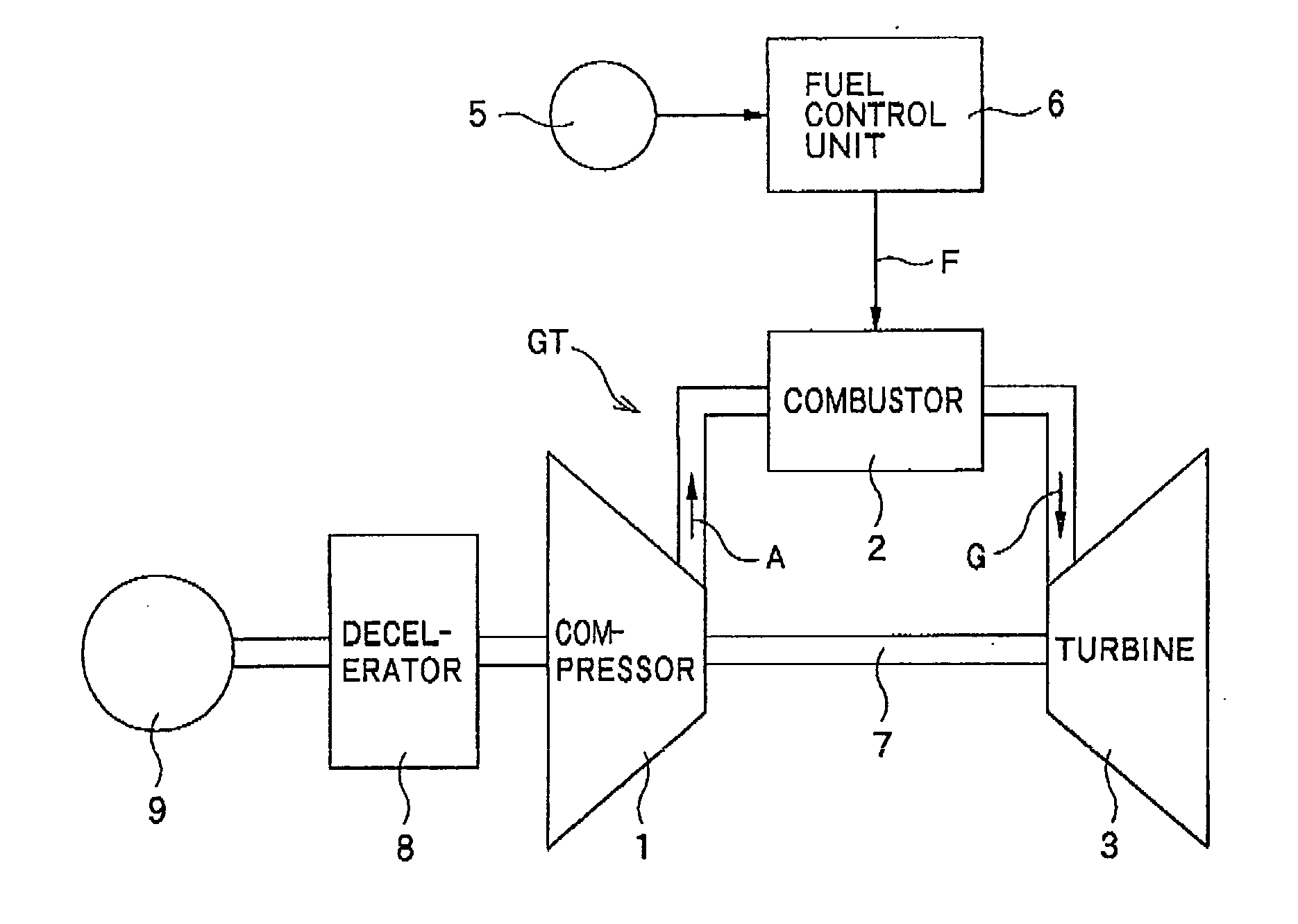
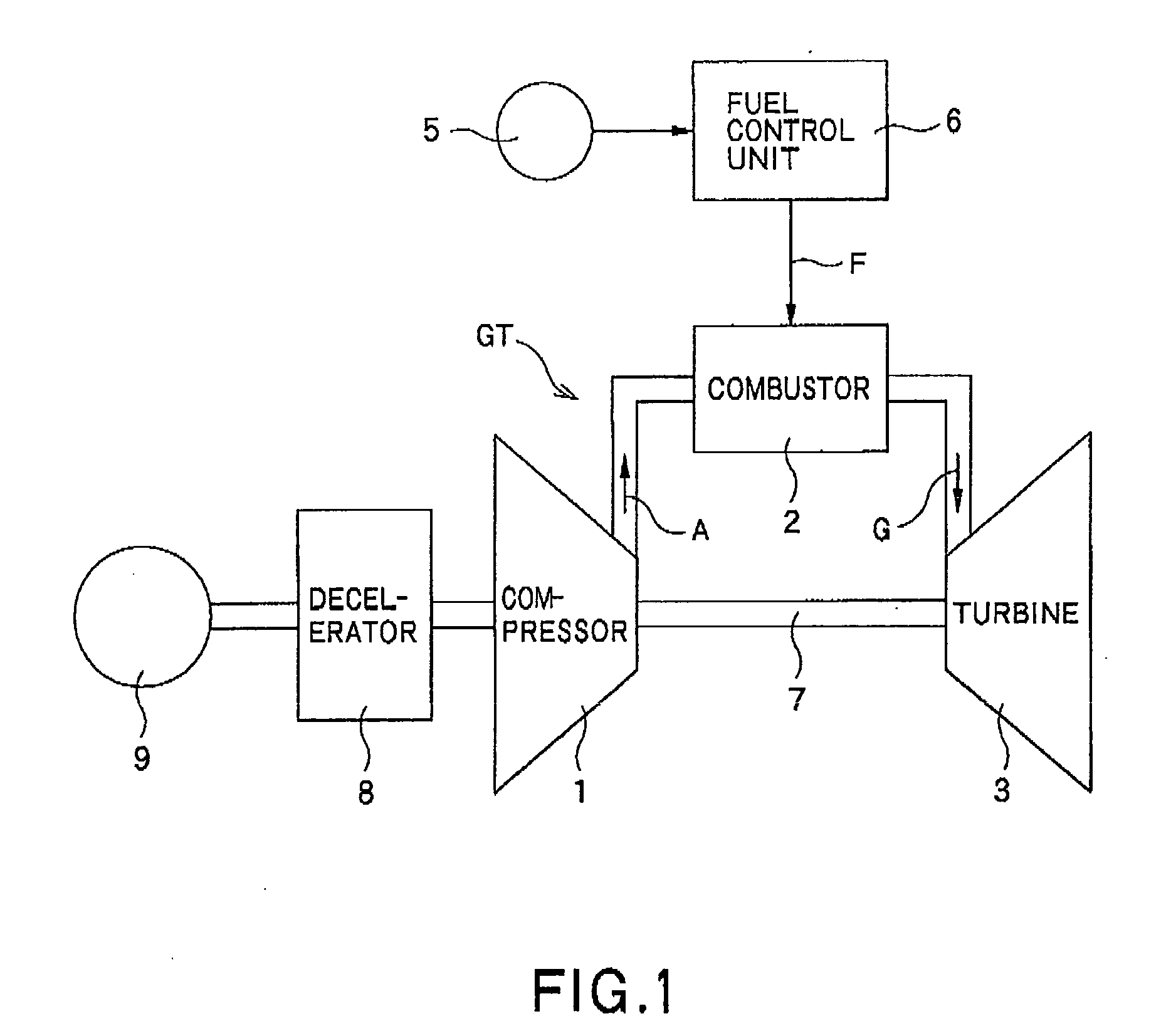
[0041]Hereinafter, several preferred embodiments will be detailed with reference to the drawings. In FIG. 1, the gas turbine GT includes the compressor 1, combustor 2 and turbine 3, as main components thereof, wherein the combustor 2 includes a fuel supply unit 5 and a fuel control unit 6. In the combustor 2, the fuel F supplied from the fuel supply unit 5 via the fuel control unit 6 can be combusted with the compressed air A supplied from the compressor 1. Thus, high-temperature and high-pressure combustion gas G generated by such combustion can be supplied to the turbine 3. As a result, the turbine 3 can be driven. Then, the compressor 1 is driven by the turbine 3 via a rotary shaft 7. Further, an electric generator 9 is driven by the turbine 3 via a decelerator 8.

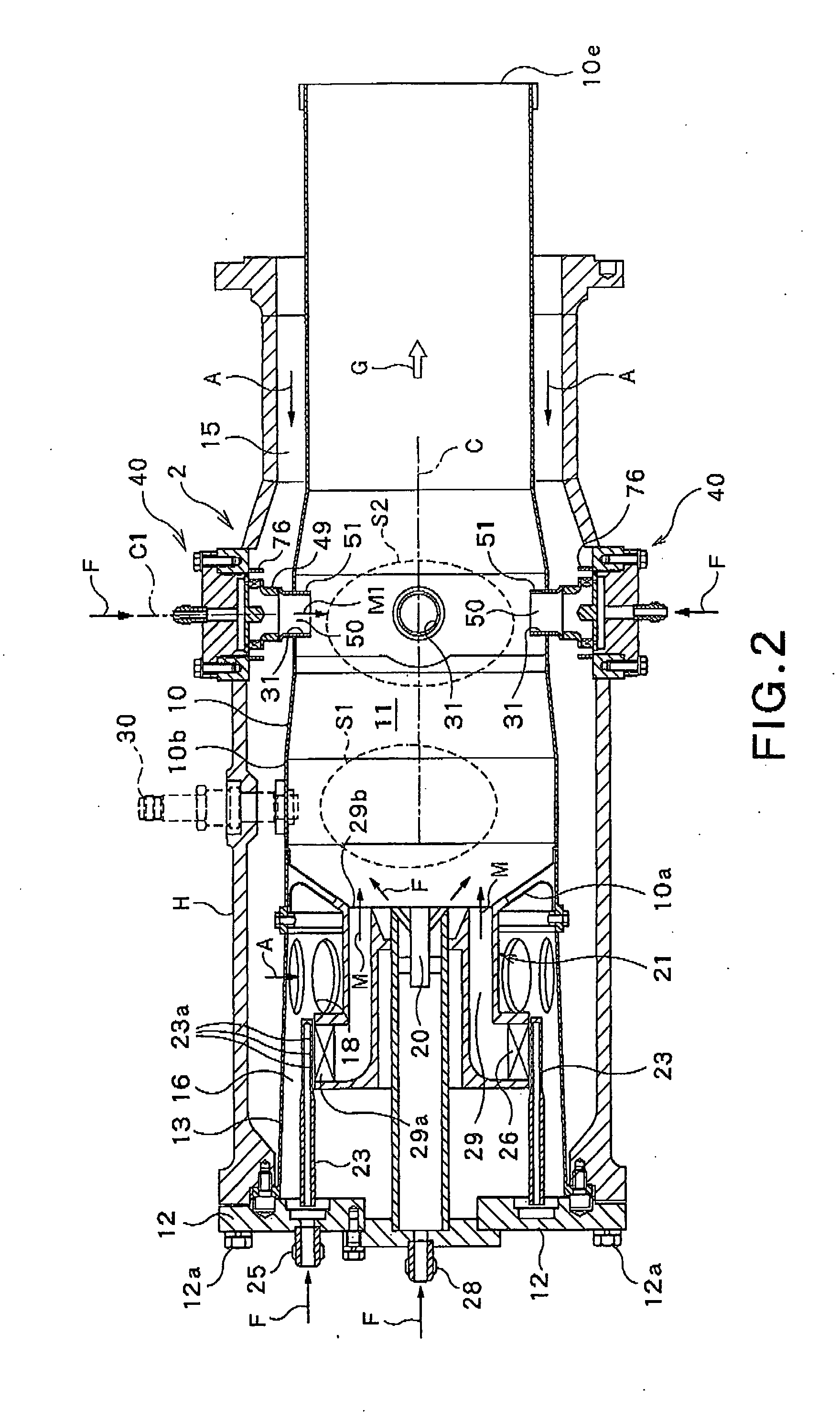
[0042]As shown in the longitudinal section of FIG. 2, the combustor 2 is of a counter-flow can type configured for allowing the compressed air A introduced therein to be flowed in a direction reverse to the direction in ...


PUM


Abstract

This invention provides a gas turbine combustor including: a main burner at a head portion of a combustor cylinder; and a pre-mixing type supplemental burner at a downstream portion of the combustor cylinder and extending through a circumferential wall thereof. The supplemental burner includes: an introducing passage configured to deflect a part of the compressed air radially inward, the compressed air flowing from an air passage between the circumferential wall of the combustor cylinder and a housing surrounding the circumferential wall toward the head portion of the combustor cylinder, and introduce the compressed air into the combustor cylinder; and a fuel nozzle configured to supply the fuel from fuel injection holes to the compressed air introduced into the introducing passage to produce a pre-mixed gas in the introducing passage.

Description

CROSS REFERENCE TO RELATED APPLICATIONS[0001]This application is based upon and claims the benefit of priority from the prior Japanese Patent Application No. 2009-60524 filed on Mar. 13, 2009, the entire contents of which are incorporated herein by reference.BACKGROUND OF THE INVENTION[0002]1. Field of the Invention[0003]The present invention relates to a gas turbine combustor which can suppress the amount of nitrogen oxides (hereinafter referred to as “NOx”) discharged from the combustor, even when the combustor is operated with a relatively high load or intensity.[0004]2. Background Art[0005]For the gas turbine apparatus, a highly strict environmental standard is established on the composition of exhaust gas discharged from the turbine upon the operation thereof. Especially, in this standard, substantial reduction of the discharge amount of NOx contained in the exhaust gas is required. In the past, as one approach for reducing the discharge amount of NOx in regard to the gas turbi...

Claims


Application Information

Patent Timeline
Patent Type & Authority Applications(United States)
IPC IPC(8): F02C7/22F23R3/42
CPCF23R3/346F23R3/34
Inventor MATSUMOTO, KIYOSHIODA, TAKEO
Owner KAWASAKI HEAVY IND LTD
Why Eureka
Try Eureka