Instrumentation and Monitoring System For Pipes and Conduits Transporting Cryogenic Materials

a monitoring system and pipe technology, applied in the direction of instruments, mechanical equipment, optical elements, etc., can solve the problems of limited insulation, high operating and maintenance costs of such systems, short-distance loading and offloading hoses, etc., to improve mechanical stability and desirable thermal insulation properties, mechanically simple structure, the effect of reducing the cost of operation and maintenan

Inactive Publication Date: 2010-09-16
ASTRO TECH GRP LLC
View PDF3 Cites 42 Cited by
  • Summary
  • Abstract
  • Description
  • Claims
  • Application Information

AI Technical Summary

Benefits of technology

[0020]The subject invention is directed to instrumentation of pipelines for transporting material at sub-ambient temperature and especially cryogenic material constructed in a manner such that the pipeline has both increased mechanical stability and desirable thermal insulation properties while maintaining a mechanically simple structure. The configurations of

Problems solved by technology

Although such terminals exist—they have been widely used for loading of crude oil and oil products for many years—no offshore terminals for LNG are in use.
The former is limited to short-distance loading and offloading hoses because of the high expense and the limitation of insulation that can be provided.
While low pressure or vacuum systems can provide excellent insulation, operation and maintenance of such systems tends to be costly, and frequently becomes problematic where such pipelines are submerged on, or even below the sea bed.
Other difficulties are also often encountered, most typically associated with thermal expansion/contraction due to cool

Method used


Image

  • Instrumentation and Monitoring System For Pipes and Conduits Transporting Cryogenic Materials
  • Instrumentation and Monitoring System For Pipes and Conduits Transporting Cryogenic Materials
  • Instrumentation and Monitoring System For Pipes and Conduits Transporting Cryogenic Materials

Examples


Embodiment Construction

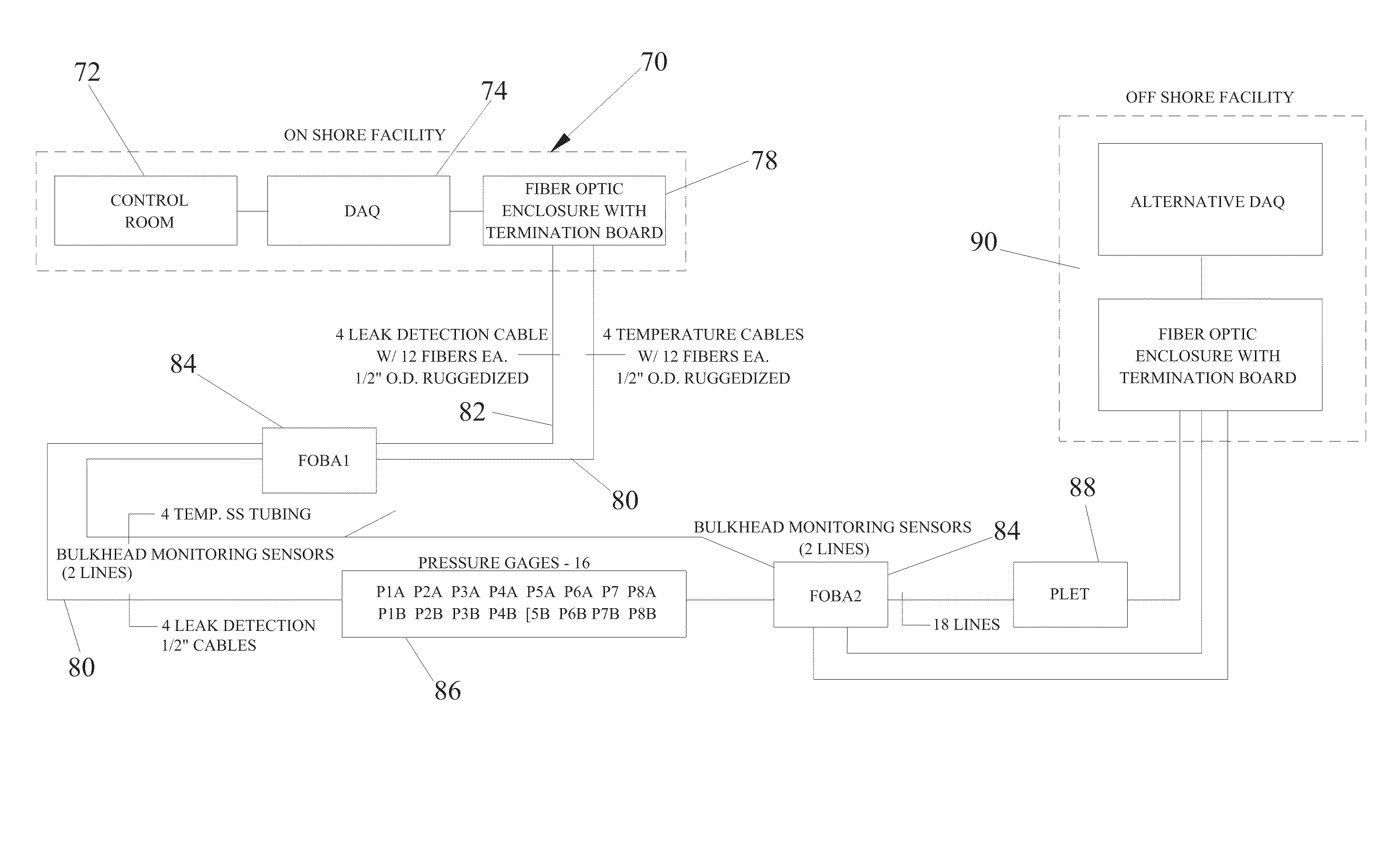
[0052]The major components and design criteria of the monitoring system are as follows:[0053]Multiple pipelines. For purposes of discussion, two LNG pipelines, 8 km in length will be discussed, containing multiple fiber optic lines for temperature, pressure, leaks and strain monitoring. The remaining components listed here are consistent with the example of two LNG pipelines, 8km in length. It should be understood that the teachings of the invention can be incorporated in additional multiple pipeline configurations of varying length and the following components would be modified to correspond to the specific configuration. The described example should not be considered as limiting, but merely exemplary.[0054]Two multi-product lines, 8 km in length containing multiple fiber optic lines for temperature, pressure, leaks and strain monitoring.[0055]One NGL cool-down line, 8km in length containing multiple fiber optic lines for temperature, pressure, leaks and strain monitoring.[0056]Lea...


PUM


Abstract

An instrumentation and monitoring system for a cryogenic material transfer system incorporates a pipe-in-pipe configuration with either a vacuum or a nanoporous or microporous insulating layer filling the annulus between the inner and outer pipe. The insulating layer is of sufficient flexibility to absorb the expansion or contraction of the inner pipe due to thermal effects from the flow of cryogenic material. The monitoring system typically includes a multitude of fiber optic sensors that measure leaks, temperature, pressure and strain. The invention includes the fiber optic sensors, conventional sensors, cabling, connectors/splice assembles, ingress/egress methods, ruggedization methods, data acquisition and analysis.

Description

CROSS REFERENCE TO RELATED APPLICATION [0001]This application is a continuation-in-part of U.S. patent application Ser. No. 12 / 150,425, which was filed on Apr. 28, 2008, which claims priority under U.S. Provisional Application No. 60 / 914,756, which was filed on Apr. 29, 2007, both of which are incorporated herein by reference.BACKGROUND OF THE INVENTION[0002]1. Field of the Invention[0003]The invention is generally related to instrumentation methods for monitoring and measuring temperature, pressure, leaks and mechanical properties in pipes or conduits for carrying cryogenic materials and is specifically directed to a pipeline system including fiber optic sensor instrumentation systems and methods.[0004]2. Discussion of the Prior Art[0005]Pipeline transfer of cryogenic fuels and other liquids such as liquid natural gas (LNG) is commonplace throughout the world. In fact, LNG is currently the fastest growing hydrocarbon fuel in the world. While gas as a primary fuel source is forecast...

Claims


Application Information

Patent Timeline
IPC IPC(8): G01M19/00G02B6/44G01M99/00
CPCF16L59/141G02B6/4427G02B6/443G02B6/502
Inventor BROWER, DAVID V.
Owner ASTRO TECH GRP LLC
Why Eureka
Try Eureka