

Polarizing plate, manufacturing method thereof, optical film and image display
a technology of optical film and polarizing plate, which is applied in the direction of polarizing elements, non-linear optics, instruments, etc., can solve the problems of reducing the yield of polarizing plate and reducing the productivity of polarizing plate, affecting the yield of polarizing plate and reducing the production cost. , to achieve the effect of reducing the production cost and reducing the generation of knick defects
Inactive Publication Date: 2010-09-16
NITTO DENKO CORP +1
View PDF14 Cites 25 Cited by
- Summary
- Abstract
- Description
- Claims
- Application Information
AI Technical Summary
Benefits of technology
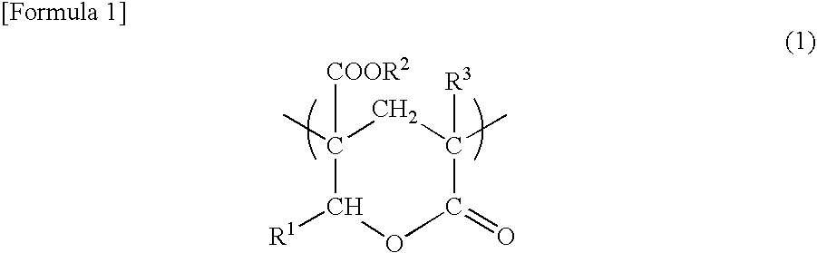
[0021]In an embodiment of the present invention, a transparent protective film containing a lactone ring structure-containing (meth)acrylic resin is used in the polarizing plate. The lactone ring structure-containing (meth)acrylic resin has a low water-vapor permeability but can satisfy durability requirements such as heat resistance under high temperature environment and humidity resistance under high humidity environment and also satisfy display uniformity (unevenness) requirements, without causing degradation of the optical properties.
[0053]In an embodiment of the present invention, the transparent protective film may contain an additional thermoplastic resin in addition to the lactone ring structure-containing (meth)acrylic resin. The additional thermoplastic resin is preferably one that is thermodynamically compatible and capable of increasing the transparency or mechanical strength.
[0025]A polyvinyl alcohol-based resin may be used for an adhesive for polarizing plate to form the adhesive layer. In a particularly preferred embodiment of the present invention, a polyvinyl alcohol-based resin having an acetoacetyl group is used as the polyvinyl alcohol-based resin. The adhesive using the polyvinyl alcohol-based resin having an acetoacetyl group can form an adhesive layer with good water resistance. On the other hand, when a polyvinyl alcohol-based resin having an acetoacetyl group is used in conventional adhesive for polarizing plate, the occurrence of knick defects is frequently observed. However, the adhesive for polarizing plate of the present invention includes the colloidal metal compound and thus can reduce the occurrence of knick defects even when a polyvinyl alcohol-based resin having an acetoacetyl group is used in the adhesive for polarizing plate. Thus, there is provided an adhesive for polarizing plate having water resistance and capable of reducing the occurrence of knick defects.
Problems solved by technology
However, the use of a triacetylcellulose film as a transparent protective film is more likely to cause unevenness, because it has high water-vapor permeability and high photoelastic coefficient.
On the other hand, when a polyethylene terephthalate film or a norbornene-based film, which has low water-vapor permeability, is used as a transparent protective film in a polarizing plate, water cannot be released from the polarizer, so that a steam-heated state is brought about, which contrarily degrades the optical properties.
Therefore, the process of preparing a polarizing plate has a problem in which knick defects may occur when the polarizer and the transparent protective film are bonded together.
Knick defects are defects of local irregularities formed at the interface between the polarizer and the transparent protective film.
Knick defects are particularly easy to occur when a polyvinyl alcohol-based resin having an acetoacetyl group is used for the polyvinyl alcohol-based adhesive.
Method used
View moreImage
Smart ImageViewing Examples

Examples
example 1
Preparation of Polarizing Plate
[0175]Adhesive 1 was applied to one side of transparent protective film 1 so that the adhesive layer could have a thickness of 80 nm after drying. Adhesive 1 was applied to one side of transparent protective film 2 so that the adhesive layer could have a thickness of 80 nm after drying. The adhesive was applied at a temperature of 23° C. 30 minutes after the preparation of the adhesive. The adhesive-carrying transparent protective films 1 and 2 were bonded to both sides of the polarizer at a temperature of 23° C. with a roller and then dried at 55° C. for 6 minutes, so that a polarizing plate was obtained.
Login to View More PUM
| Property | Measurement | Unit |
|---|---|---|
| thickness direction retardation | aaaaa | aaaaa |
| thickness direction retardation | aaaaa | aaaaa |
| particle size | aaaaa | aaaaa |
Abstract
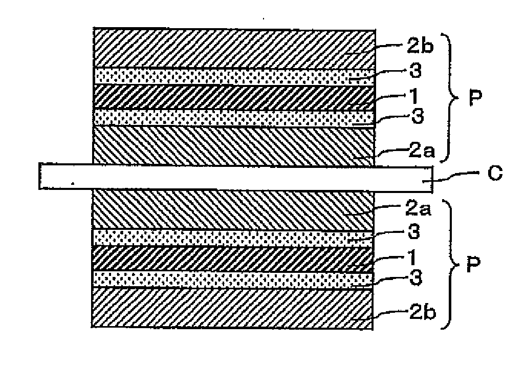
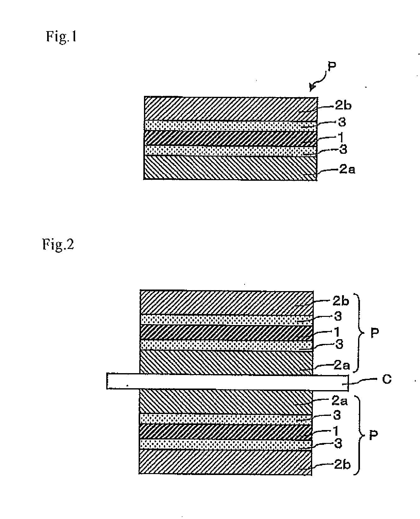
A polarizing plate of the present invention includes a polyvinyl alcohol-based polarizer and transparent protective films provided on both sides of the polarizer with an adhesive layer interposed between the polarizer and each transparent protective film, wherein the transparent protective film on one side comprises a lactone ring structure-containing (meth)acrylic resin and is a retardation plate having an in-plane retardation of 40 nm or more and / or a thickness direction retardation of 80 nm or more, and the transparent protective film on the other side has an in-plane retardation of less than 40 nm and a thickness direction retardation of less than 80 nm. The polarizing plate can satisfy durability and display uniformity (unevenness).
Description
TECHNICAL FIELD[0001]The present invention relates to a polarizing plate and a manufacturing method thereof. The polarizing plate may be used alone or as a part of a laminated optical film to form liquid crystal displays (LCDs), organic EL displays, CRTs, PDPs, and so on.BACKGROUND ART[0002]Liquid crystal displays use liquid crystal switching to visualize the polarization state, and based on the display principle, they use a polarizing plate including a polarizer and transparent protective films provided on both sides of the polarizer with an adhesive layer interposed therebetween. For example, iodine polarizers made of stretched polyvinyl alcohol to which iodine is adsorbed have high transmittance and high degree of polarization. Therefore, they are most popular polarizers widely used. Triacetylcellulose or the like has high water-vapor permeability and therefore is used for transparent protective films.[0003]Image displays such as liquid crystal displays as an application of the p...
Claims
Login to View More Application Information
Patent Timeline
 Patent Type & AuthorityApplications(United States)
IPC IPC(8): G02B5/30B32B17/10
CPCB29C66/45B29C65/482B29K2105/0079B29K2995/0026B29K2995/0034B29L2009/00B29L2011/0066B32B7/12B32B37/12B32B2307/412B32B2307/42B32B2457/20G02B1/105G02B5/3083B29C65/4845B29C65/4865B29C65/48B29C65/4815B29C65/4825B29C65/483B29K2029/00B32B27/08B32B27/306B32B27/308B32B2255/10B32B2255/26B32B2264/10B32B2307/306B32B2307/40B32B2307/7246B32B2457/202G02B1/14
InventorKOBAYASHI, KANTOSUGINO, YOUICHIROUUEDA, NARIFUMI
OwnerNITTO DENKO CORP