Radiation/Drug Delivery Method and Apparatus

a technology of radiotherapy and drug delivery, applied in the direction of radiation therapy, therapy, etc., can solve the problems of inability to accurately place seeds, lack of precision in positioning seeds, and inability to use sutures in deep tissues, etc., to achieve effective delivery, facilitate multiple treatment sessions, and minimal invasive

Inactive Publication Date: 2010-09-16
ARMSTRONG KEVIN +1
View PDF7 Cites 10 Cited by
  • Summary
  • Abstract
  • Description
  • Claims
  • Application Information

AI Technical Summary

Benefits of technology

[0040]In further contrast to the prior art brachytherapy methods and devices set forth above, the features of the present invention facilitate multiple treatment sessions with minimal invasiveness to the patient who would otherwise have to endure repeated surgical placement of catheters or mutiple needles to attain effective delivery of a brachytherapy radiation source or other therapeutic agents.
[0041]As will be appreciated by those skilled in the art, the device and method of the present invention also allows for the removal of the therapeutic agent between treatment sessions with minimal discomfort to the patient. Such an advantage further provides the physician with various options by which he c

Problems solved by technology

Techniques involving such guns or needles to implant seeds have proved to be deficient in many respects, primarily because they do not provide a means for implanting seeds at a precise spacing and location to perform the desired treatment.
Such a suture approach had limited applicability in deep tissues so the same basic idea was employed using a needle to inject seeds separated by absorbable spacers.
According to Scott, this device was a vast improvement over previous techniques yet it lacked some precision in positioning the seeds because the method of ejecting seeds from the needle functioned imperfectly.
Terwilliger points out that despite any differences in the foregoing approaches, such techniques typically result in the radioactive seeds being deposited in the track made by the needle.
As the needle is withdrawn, there is a tendency for the seeds to migrate in the needle track resulting in a poor distribution of the seeds and compromising the intended sphere of radiation.
Terwilliger further points out that these seeds often continue to migrate over time resulting in the need for additional implant sessions that are costly and uncomfortable for the patient.
Unfortunately, such implants have many drawbacks including positioning problems as well as the inability of the implant to flex with the tissue over the time necessary for the bio-absorbable material to dissolve.
Accordingly, the final location relative to the tumor site is not maintained and the dosage of the radioactive seeds does not meet the preoperative therapy plan.
The difference in diameter between the seed and the thin suture material makes the assembly susceptible to collapse from axial force applied on the proximal end, thereby resulting in the assembly typically becoming jammed within the needle lumen and/or the assembly not maintaining the proper desired spacing between radioactive seeds as it is positioned into the treatment site.
While the permanence of such implantation may be somewhat limited due to the radioactive half-life of the isotopes employed as well as the biodegradable nature of the containment housings or other vehicles implanted along with such isotopes, the permanence or semi-permanence is clearly a prior art shortcoming based upon the increased exposure of the patient to the resulting radioactivity over an extended

Method used


Image

  • Radiation/Drug Delivery Method and Apparatus
  • Radiation/Drug Delivery Method and Apparatus
  • Radiation/Drug Delivery Method and Apparatus

Examples


example 1

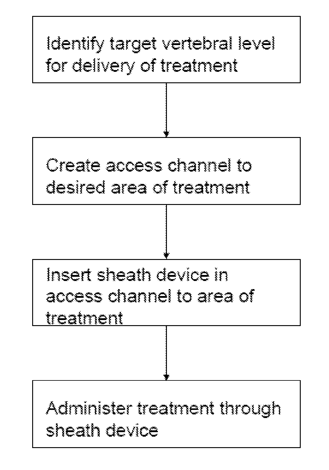
[0082]The invented method will first entail locating the insertion point to the desired area of treatment. Placing the patient in an appropriate position, the clinician can use a C-arm to identify the appropriate vertebral body or bony tumor location in the desired entry point into the pedicle, vertebral body or bone.

[0083]Next, a physical channel to the tumor treatment area needs to be created. There are many methodologies known in the art for creating such a channel. Each method has its respective advantages. Accordingly, it will be apparent to the physician that the choice of such methods will depend upon the nature and path of the channel to be created.

[0084]For example, utilizing a cannulated or non-cannulated jam sheedy or other appropriate instrument, the clinician can advance the instrument into the vertebral body placing its tip in the desired location relative to the tumor. In the event a cannulated needle is used, the trocar will be removed from the needle. In another exe...

example 2

[0085]After the hole has been expanded, if the bone cannula has the aforementioned opening in the end or the long tube style is used, the cannula can be delivered over the k-wire or a drill or pedicle finder and the k-wire will be removed and the bone cannula can be advanced into the cavity that has been created. A balloon catheter can then be advanced into the bore in the bone cannula and the therapeutic entity can be delivered to the desired tumor location in the appropriate dosage. In the event that serial therapy should be desired prior to removal of the cannula, appropriate wound care management should be provided during the period that the bone cannula remains in the patient. In the event that serial therapy should occur over a several day period, a catheter may be removed and replaced with a trocar that is positioned within the bone cannula followed by appropriate wound closure techniques. Upon the next desired treatment session, a k-wire may be used to re-introduce the dilat...


PUM


Abstract

There is provided herein a brachytherapy delivery system for the internal delivery and positioning of therapeutic agent, most particularly, a discrete radiation emitting particulate, within or in proximity to a vertebral or other bony tumor. The system comprises an elongated bone cannula having a proximal and a distal end, the distal end being suitable for disposition within bone. The bone cannula further comprises a bore disposed longitudinally therethrough suitable to axially and slidably receive an elongated and cannulated therapy delivery apparatus through which the therapeutic agent is delivered.

Description

CROSS-REFERENCE TO RELATED RELATED APPLICATION[0001]This application claims the benefit under 35 U.S.C. §119 (e) of U.S. Provisional Application Ser. No. ______, filed Mar. 11, 2008, which is hereby incorporated in its entirety by reference thereto.BACKGROUND OF THE INVENTION[0002]The present invention relates to methods and devices for administering radiation and / or pharmaceutical or other therapeutic agents into bony tissues, especially vertebral bone. More particularly, the present invention relates to methods and devices for treating tumors in vertebral bone.[0003]Methodologies utilizing localized radiation and / or pharmaceuticals and chemotherapeutic agents to treat many different types of tumors are well known in the art of medicine. One particular type of such treatment commonly referred to as brachytherapy, delivers a radiation dose to soft tissue tumors by way of a discrete radiation source that is positioned in or within close proximity to the tumor site. Most conventional ...

Claims


Application Information

Patent Timeline
IPC IPC(8): A61M36/12
CPCA61N5/1027A61N5/1007
Inventor ARMSTRONG, KEVINCHEN, THOMAS
Owner ARMSTRONG KEVIN
Why Eureka
Try Eureka