Light source apparatus and projector

a light source and projector technology, applied in semiconductor lasers, instruments, cladded optical fibres, etc., can solve the problems of limited color reproducibility, short life, and difficulty in quick start and shutoff, and achieve the effects of high brightness, large dynamic range, and high quality

Inactive Publication Date: 2010-09-23
SEIKO EPSON CORP
View PDF8 Cites 26 Cited by
  • Summary
  • Abstract
  • Description
  • Claims
  • Application Information

AI Technical Summary

Benefits of technology

[0041]Since any of the light source apparatus based on the first aspect of the invention produces high-intensity light, the high-intensity light is modulated by the modulator and then displayed through the display system. An image displayed by the projector therefore has high brightness, a large dynamic range, and high quality. Further, the light source apparatus can be manufactured at a lower cost than a case where a lamp-based light source, for example, using a discharge arc tube is us

Problems solved by technology

An advantage of a high-pressure mercury lamp includes high intensity of the emitted light, but disadvantages thereof include limited color reproducibility, difficulty of quick start and shut off, and a short life.
In the laser light source apparatus disclosed in JP-A-5-48200, however, the configuration in which the collector lens is separate from the light emitter makes it difficult to improve the positional precision of the collector lens relative to the light emitter and the positional precision of the collector lens relative to the external reflection mirror.
Alignment based on an XY stage or any other similar positioning apparatus is limited in terms of precision because improvement in positional precis

Method used


Image

  • Light source apparatus and projector
  • Light source apparatus and projector
  • Light source apparatus and projector

Examples


first embodiment

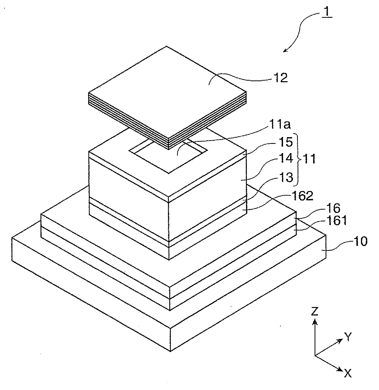
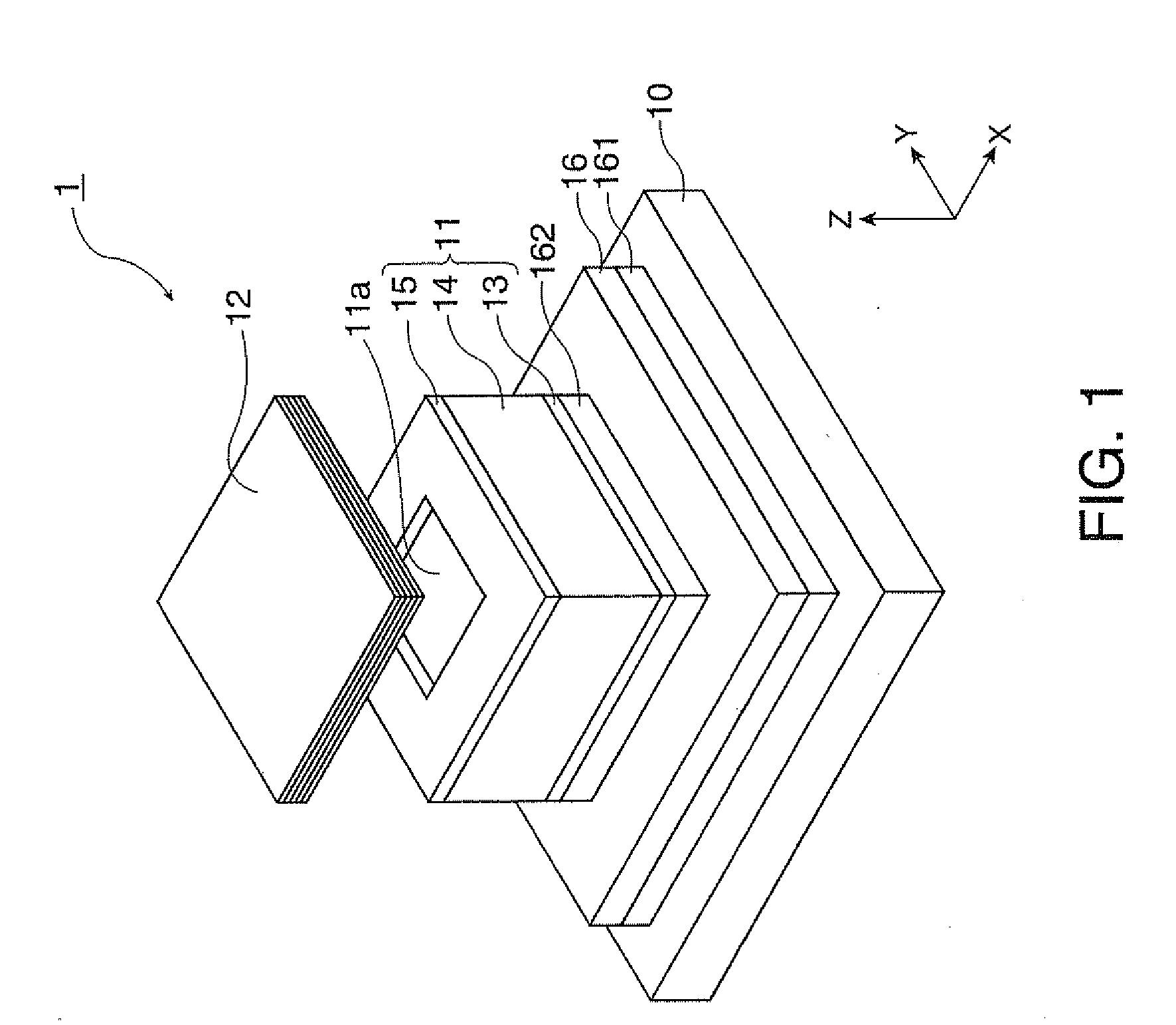
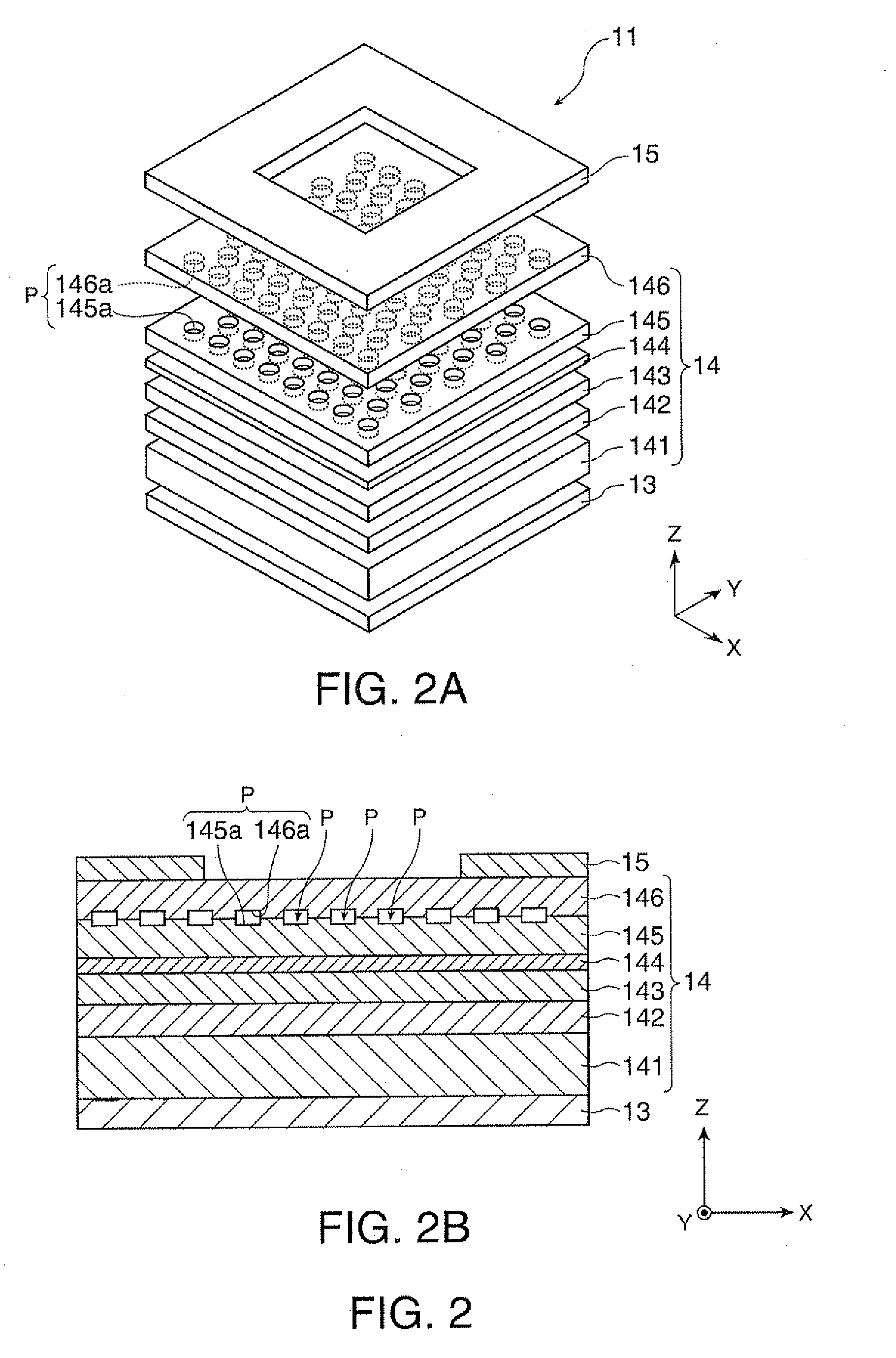
[0058]FIG. 1 is a perspective view showing a schematic configuration of a light source apparatus 1 according to a first embodiment. As shown in FIG. 1, the light source apparatus 1 includes a heat sink (heat spreading member) 10, a light emitter 11, and an external mirror 12. The heat sink 10 in the present embodiment is a plate-shaped member. The direction normal to one side of the heat sink 10 is the direction of a principal optical axis of the light source apparatus 1. The light emitter 11 and the external mirror 12 are disposed in this order in the direction of the principal optical axis of the light source apparatus 1 from the heat sink 10. In the present embodiment, each of the light emitter 11 and the external mirror 12 has a substantially oblong shape when viewed from the above (a substantially square shape in FIG. 1).

[0059]In the following description, the positional relationship of the members will be described based on the XYZ orthogonal coordinate system set and shown in...

second embodiment

[0094]A light source apparatus according to a second embodiment will be described. The second embodiment differs from the first embodiment in terms of the following points: The second electrode of the light emitter is formed of a wire grid optical polarizer. The external mirror is formed of a VHG. A wavelength conversion device is provided between the light emitter and the external mirror.

[0095]FIG. 7 is a perspective view showing a schematic configuration of a light source apparatus 2 according to the second embodiment. As shown in FIG. 7, the light source apparatus 2 includes a heat sink 20, a light emitter 21, and an external mirror 22. The direction perpendicular to the plane (XY plane) across which the heat sink 10 extends is the direction of the principal optical axis of the light emitter 21. The heat sink 20, the light emitter 21, the wavelength conversion device 27, and the external mirror 22 are disposed in this order in the direction of the principal optical axis, as in th...


PUM


Abstract

A light source apparatus includes: a light emitter; a pair of electrodes for driving the light emitter; and an external resonant cavity that reflects part of the light emitted from a light-exiting end surface of the light emitter. The light emitter includes an active layer that generates light, an internal resonant cavity, and a diffractive optical layer that diffracts light having a predetermined wavelength. The external resonant cavity includes an external mirror that reflects the light having the predetermined wavelength. The internal resonant cavity, the external resonant cavity, and the diffractive optical layer form a laser resonant cavity that allows the light generated in the active layer to achieve laser oscillation.

Description

BACKGROUND[0001]1. Technical Field[0002]The present invention relate to a light source apparatus and a projector.[0003]2. Related Art[0004]In a field of projectors and other similar optical apparatus, a high-pressure mercury lamp has been extensively used as an illumination light source. An advantage of a high-pressure mercury lamp includes high intensity of the emitted light, but disadvantages thereof include limited color reproducibility, difficulty of quick start and shut off, and a short life. Under such circumstances, there have been expectations for laser light source apparatus using a semiconductor laser or any other suitable solid-state light source instead of a high-pressure mercury lamp. JP-A-5-48200 and U.S. Pat. No. 6,404,797 disclose exemplary semiconductor laser devices.[0005]The external-cavity wavelength-tunable semiconductor laser apparatus disclosed in JP-A-5-48200 includes a Fabry-Perot resonator-based semiconductor laser device (light emitter) and a collector len...

Claims


Application Information

Patent Timeline
IPC IPC(8): H01S3/08
CPCB82Y20/00G03B21/2033G02B6/02057G02B6/1225G02B6/4204G02F1/3775G02F2202/32H01S3/109H01S5/024H01S5/0425H01S5/105H01S5/141H01S5/146H01S5/18311H01S5/1835H01S5/18355H01S5/18391H01S5/34313G03B21/2066G02B1/005H01S5/04254H01S5/11
Inventor MOCHIZUKI, MASAMITSU
Owner SEIKO EPSON CORP
Why Eureka
Try Eureka