Sputtering Target for Magnetic Recording Film and Method for Manufacturing the Same

a technology of magnetic recording film and sputtering target, which is applied in the direction of diaphragms, metallic material coating processes, electrical devices, etc., can solve the problems of not fully suppressing crystal grain growth, and achieve the reduction of particle and arcing, high density, and low magnetic permeability

Inactive Publication Date: 2010-09-30
MITSUI MINING & SMELTING CO LTD
View PDF8 Cites 16 Cited by
  • Summary
  • Abstract
  • Description
  • Claims
  • Application Information

AI Technical Summary

Benefits of technology

[0015]The sputtering target for a magnetic recording film in accordance with the present invention is a sputtering target that has a high density and in which a growth of a crystal grain is fully suppressed. Consequently, an occurrence of a particle and an arcing can be reduced. Moreover, the sputtering target has a low magnetic permeability, thereby improving a sputter rate. In addition, a high speed film formation can be implemented in the case in which the sputtering target is sputtered to form a magnetic recording film.
[0016]Moreover, by the method for manufacturing a sputtering target for a magnetic recording film in accordance with the present invention, the sputtering target can be obtained easily at a high speed, whereby the efficiency for manufacturing processes can be improved.

Problems solved by technology

However, since a sintering temperature in manufacturing the target is relatively high in the range of 1000 to 1300° C., a growth of a crystal grain is not fully suppressed.

Method used


Image

  • Sputtering Target for Magnetic Recording Film and Method for Manufacturing the Same
  • Sputtering Target for Magnetic Recording Film and Method for Manufacturing the Same
  • Sputtering Target for Magnetic Recording Film and Method for Manufacturing the Same

Examples


embodiment 1

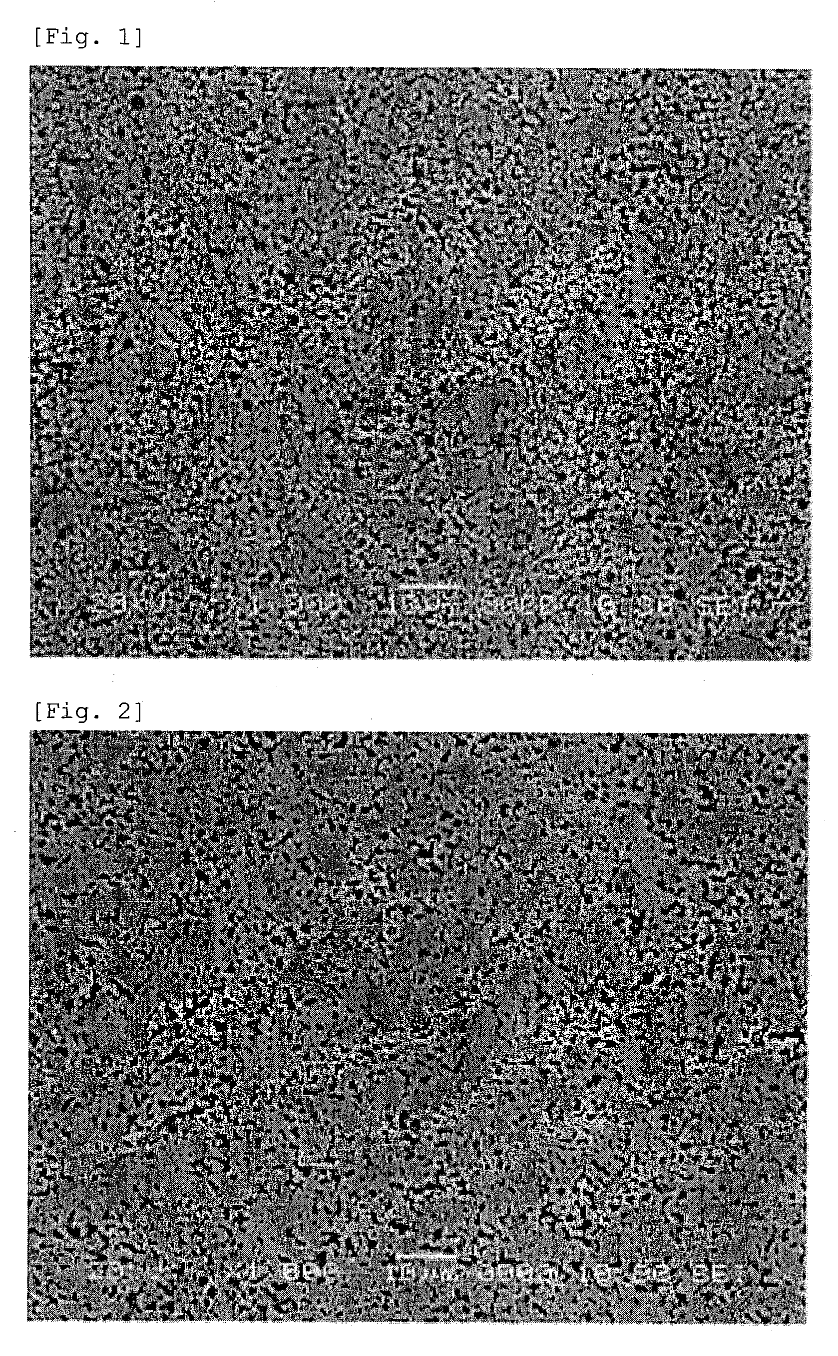
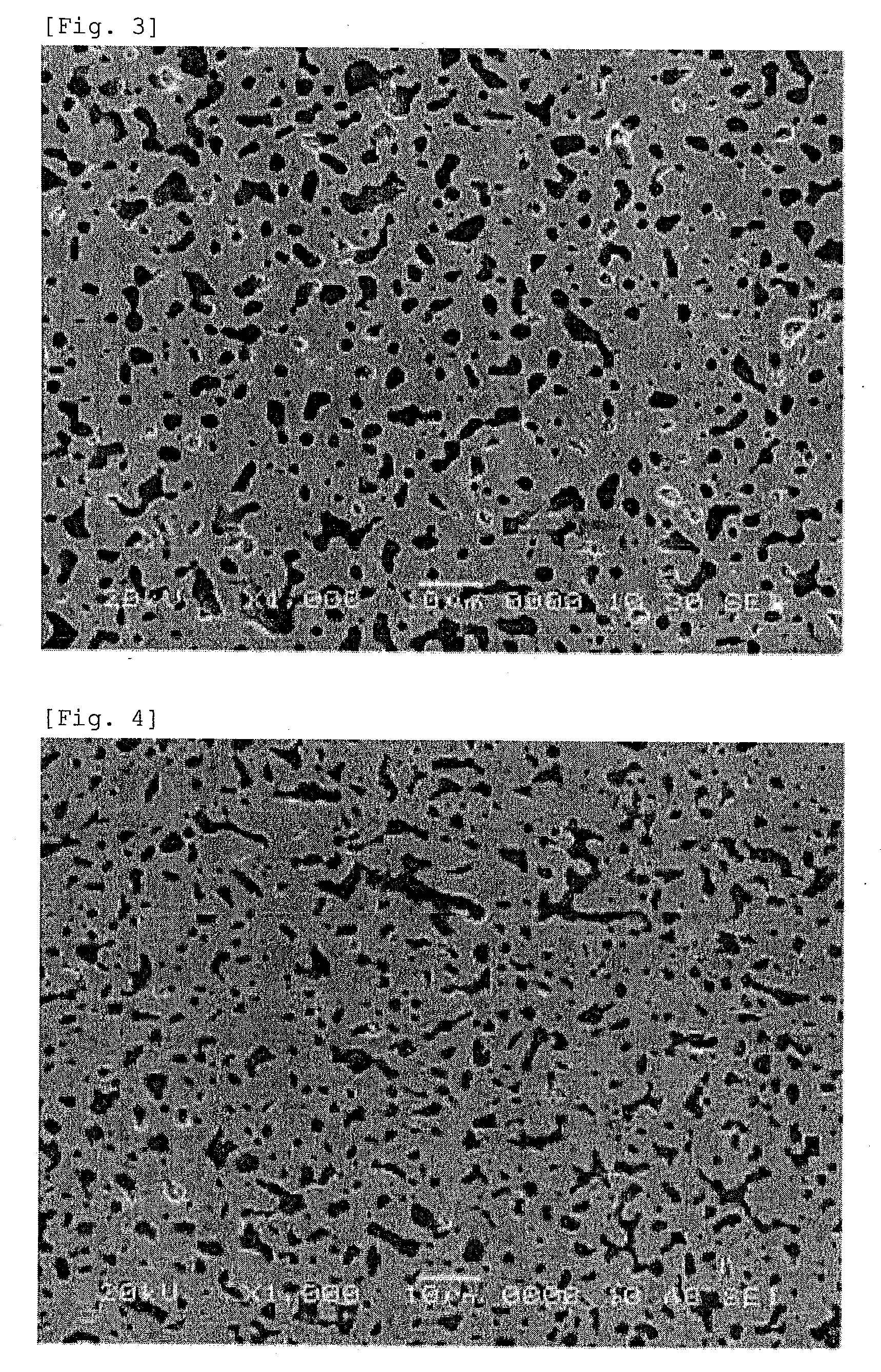
[0072]An alloy of CoCr of 2 kg was atomized by injecting an Ar gas of 50 kg / cm2 under the condition of a tapping temperature of 1650° C. (measured by using a radiation thermometer) by using a microminiature gas atomizing apparatus (manufactured by NISSIN GIKEN CO., LTD.) to obtain a powder. The obtained powder was a powder in a spherical shape having an average grain diameter of 150 μm or less.

[0073]In the next place, by using the obtained powder and a TiO2 powder (having an average grain diameter of approximately 0.5 μm), a mechanical alloying process was carried out by using a ball mill to obtain the powder (A).

[0074]A Pt powder (having an average grain diameter of approximately 0.5 μm) and a powder similar to the Co powder were further input to the obtained powder (A), and the powders were mixed to have a compositional ratio of CO66Cr10Pt15 (TiO2)9, whereby the powder (B) was obtained. A ball mill was used for mixing.

[0075]Moreover, the grain size regulation of the obtained powde...

embodiments 2 to 4

, Reference Examples 1 and 2

[0080]By using powders similar to those of Embodiment 1, the powders were mixed to have a compositional ratio shown in Table 1, whereby the powder (B) was obtained. Similarly to Embodiment 1 except for the sintering conditions shown in Table 1, a sputtering target of φ4 inches was obtained. The measuring results using the sintered object are shown in Table 1.

embodiments 5 to 7

, Reference Examples 3 and 4

[0084]By using an SiO2 powder (having an average grain diameter of approximately 0.5 μm) as substitute for the TiO2 powder, the powders were mixed to have a compositional ratio shown in Table 1, whereby the powder (B) was obtained. Similarly to Comparative example 1 except for the sintering conditions shown in Table 1, a sputtering target of 0 inches was obtained. The measuring results using the sintered object are shown in Table 1.


PUM

PropertyMeasurementUnit
grain diameteraaaaaaaaaa
temperatureaaaaaaaaaa

Abstract

Provided is a sputtering target for a magnetic recording film, in which film formation efficiency and film characteristics can be improved by suppressing growth of crystal grains, reducing magnetic permeability, and increasing density. A method for manufacturing such a sputtering target is also provided. The sputtering target is composed of a matrix phase which includes Co and Pt and a metal oxide phase for example. The sputtering target has a magnetic permeability in the range of 6 to 15 and a relative density of 90% or more.

Description

TECHNICAL FIELD[0001]The present invention relates to a sputtering target that is used in the case in which a magnetic recording film is formed and a method for manufacturing the sputtering target. More specifically, the present invention relates to a sputtering target for a magnetic recording film that has a low magnetic permeability and a high density and a method for manufacturing the sputtering target.BACKGROUND ART[0002]A hard disk device that is adopted as an external recording device requires a high density recording performance that can be corresponded to a high performance computer and digital consumer electronics and so on. In recent years, the perpendicular magnetic recording technology that satisfies such a high density recording performance has been getting noticed. As a perpendicular magnetization film that is used for the perpendicular magnetic recording technology, an alloy magnetic film of Co series is adopted in a variety of ways. It is known that a media noise can...

Claims


Application Information

Patent Timeline
Patent Type & Authority Applications(United States)
IPC IPC(8): C23C14/34B22F3/10
CPCC22C5/04C22C19/07C22C30/00H01F41/183C22C32/0026C23C14/0688C23C14/3414C22C32/0021
Inventor KATO, KAZUTERU
Owner MITSUI MINING & SMELTING CO LTD
Why Eureka
Try Eureka