Modular optical diagnostic platform for chemical and biological target diagnosis and detection

a module-based, optical diagnostic platform technology, applied in the direction of optical radiation measurement, fluorescence/phosphorescence, spectrophotometry/monochromators, etc., can solve the problems of inflexible nature, large size, and inability to modulate, and other microscopes such as confocal microscopes have inherent resolution limitations

Inactive Publication Date: 2010-09-30
LOCKHEED MARTIN CORP
View PDF7 Cites 50 Cited by
  • Summary
  • Abstract
  • Description
  • Claims
  • Application Information

AI Technical Summary

Problems solved by technology

Other microscopes such as confocal microscopes have inherent resolution limitations due to diffraction.
Furthermore, some conventional systems, generally referred to as desktop systems, are large in size, non-modular, inflexible in nature and are relatively expensive.

Method used


Image

  • Modular optical diagnostic platform for chemical and biological target diagnosis and detection
  • Modular optical diagnostic platform for chemical and biological target diagnosis and detection
  • Modular optical diagnostic platform for chemical and biological target diagnosis and detection

Examples


Embodiment Construction

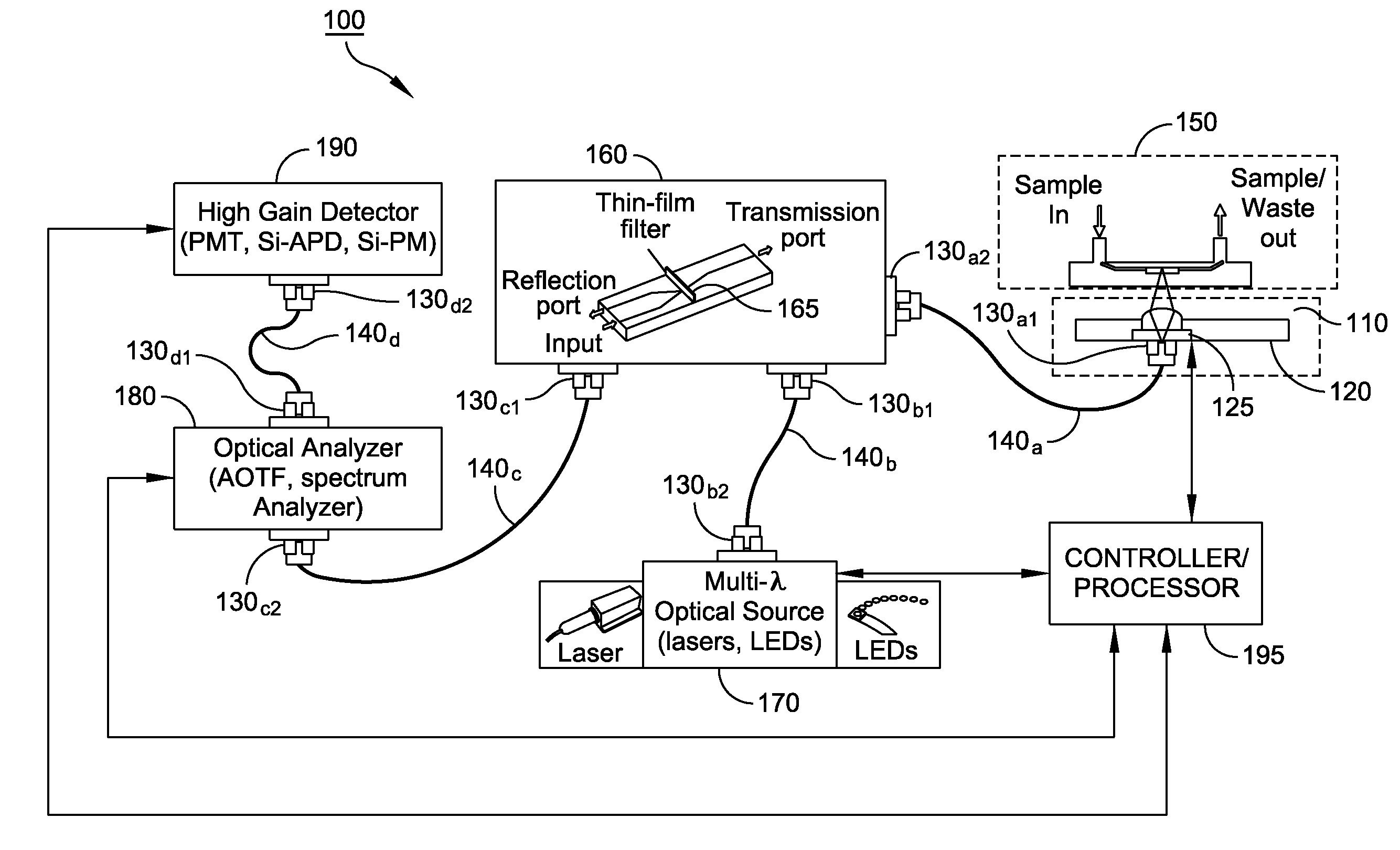
[0024]It is to be understood that the figures and descriptions of the present invention have been simplified to illustrate elements that are relevant for a clear understanding of the present invention, while eliminating, for purposes of clarity, many other elements found in typical DNA analyzer systems and fluorescence signature detection systems. However, because such elements are well known in the art, and because they do not facilitate a better understanding of the present invention, a discussion of such elements is not provided herein. The disclosure herein is directed to all such variations and modifications known to those skilled in the art.

[0025]Referring to FIG. 1, there is illustrated an exemplary modular system 100 for chemical or biological target diagnosis and detection using fluorescence signature detection, according to an embodiment of the invention. System 100 includes an optical probe 110, a sample module 150, a light source 170, an optical coupler 160, an optical a...


PUM

PropertyMeasurementUnit
lengthaaaaaaaaaa
widthaaaaaaaaaa
wavelengthsaaaaaaaaaa

Abstract

A modular system for optical diagnosis of a sample includes a portable optical probe, a light source, a filter, and a gain detector. A first optical element releasably, optically couples the optical probe to the light source. A second optical element releasably, optically couples the optical probe to the filter and a third optical element releasably, optically couples the filter to the gain detector. The optical probe receives an optical signal from the light source via the first optical element and directs the optical signal onto the sample, thereby inducing fluorescence emission from the sample. The optical probe receives the fluorescence emission from the sample and transmits to the filter via the second optical element. The filter transmits the fluorescence emission to the gain detector via the third optical element. The optical head includes a beam splitter which reflects the fluorescence emission from the sample to the filter.

Description

CROSS-REFERENCE TO RELATED APPLICATION[0001]The present application claims the benefit of the U.S. Provisional Patent Application Ser. No. 61 / 164,844, filed on Mar. 30, 2009, which application is incorporated by reference herein in its entirety.FIELD OF INVENTION[0002]The present invention relates in general to chemical and biological target detection and identification, and more particularly, to fiber optic systems and apparatus therefor.BACKGROUND[0003]Rapid and real-time detection of chemical and biological agents without the need for elaborate laboratory facilities is desirable for many applications, including medical and security applications. Generally, systems for DNA fingerprinting identification, cytometry, microscopy and fluorescence imaging, for example, have large footprints and require dedicated resources of a laboratory. Components of such systems generally require precision alignment for optical elements such as lenses and mirrors and may be specialized for a given ap...

Claims


Application Information

Patent Timeline
Patent Type & Authority Applications(United States)
IPC IPC(8): G01J1/58G01N21/64G06F19/00G01J3/30
CPCG01J3/02G01N2021/0346G01J3/021G01J3/0218G01J3/027G01J3/0289G01J3/10G01J3/1256G01J3/32G01J3/4406G01N21/05G01N21/645G01N2021/6417G01N2021/6482G01J3/0208
Inventor MAURER, SCOTTGROVES, STEPHANIEKOO, KEE
Owner LOCKHEED MARTIN CORP
Why Eureka
Try Eureka