Sensorless-Brushless Motor Control Device and Electric Fluid Pump Using the Same
a technology of motor control and motor brushless, which is applied in the direction of motor/generator/converter stopper, electronic commutator, dynamo-electric converter control, etc., can solve the problems of low performance of the electric pump driven by the motor, delay in response to current control, and high hardware structure cost, etc., to achieve smooth changeover, low cost, and high speed
- Summary
- Abstract
- Description
- Claims
- Application Information
AI Technical Summary
Benefits of technology
Problems solved by technology
Method used
Image

Examples
first embodiment
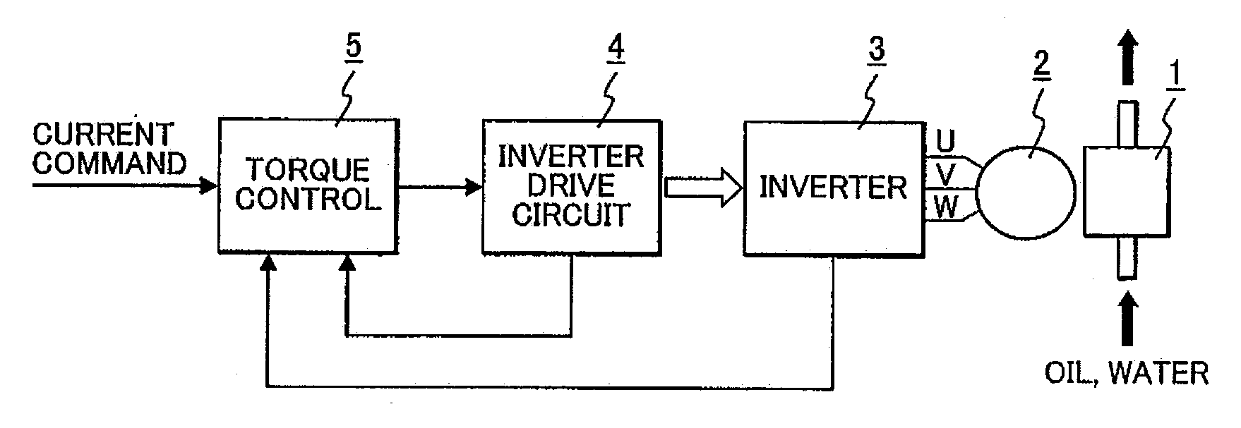
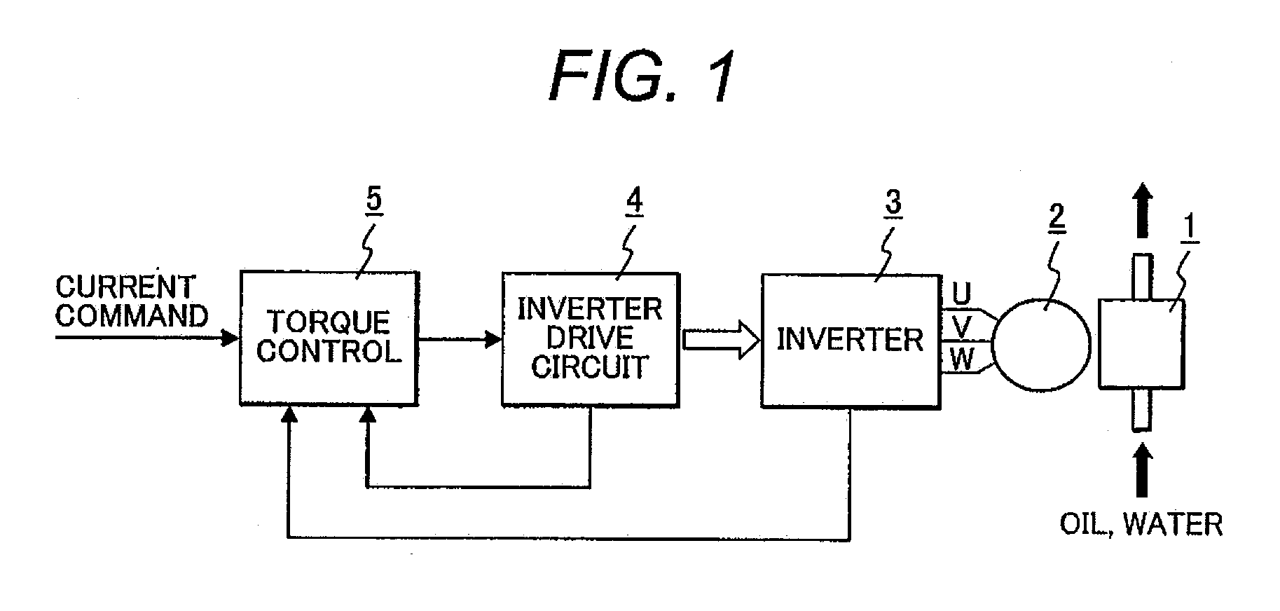
[0031]FIG. 1 is a block diagram showing a constitution of an electric fluid pump that makes use of a sensorless-brushless motor control device according to a first embodiment.
[0032]An electric fluid pump is to suck and discharge such as lubrication oil, actuator drive use oil and coolant use water. As shown in FIG. 1, the electric fluid pump 1 is driven by a sensorless-brushless motor 2 (herein below, will be simply called as “motor”) directly coupled thereto. The motor 2 is controlled and driven by a sensorless-brushless motor control device (herein below, will be simply called as “motor control device”). The motor control device comprises an inverter 3 for driving the motor 2, an inverter drive circuit 4 for controlling the inverter 3 and a torque control part 5 that outputs a control command to the inverter drive circuit 4.
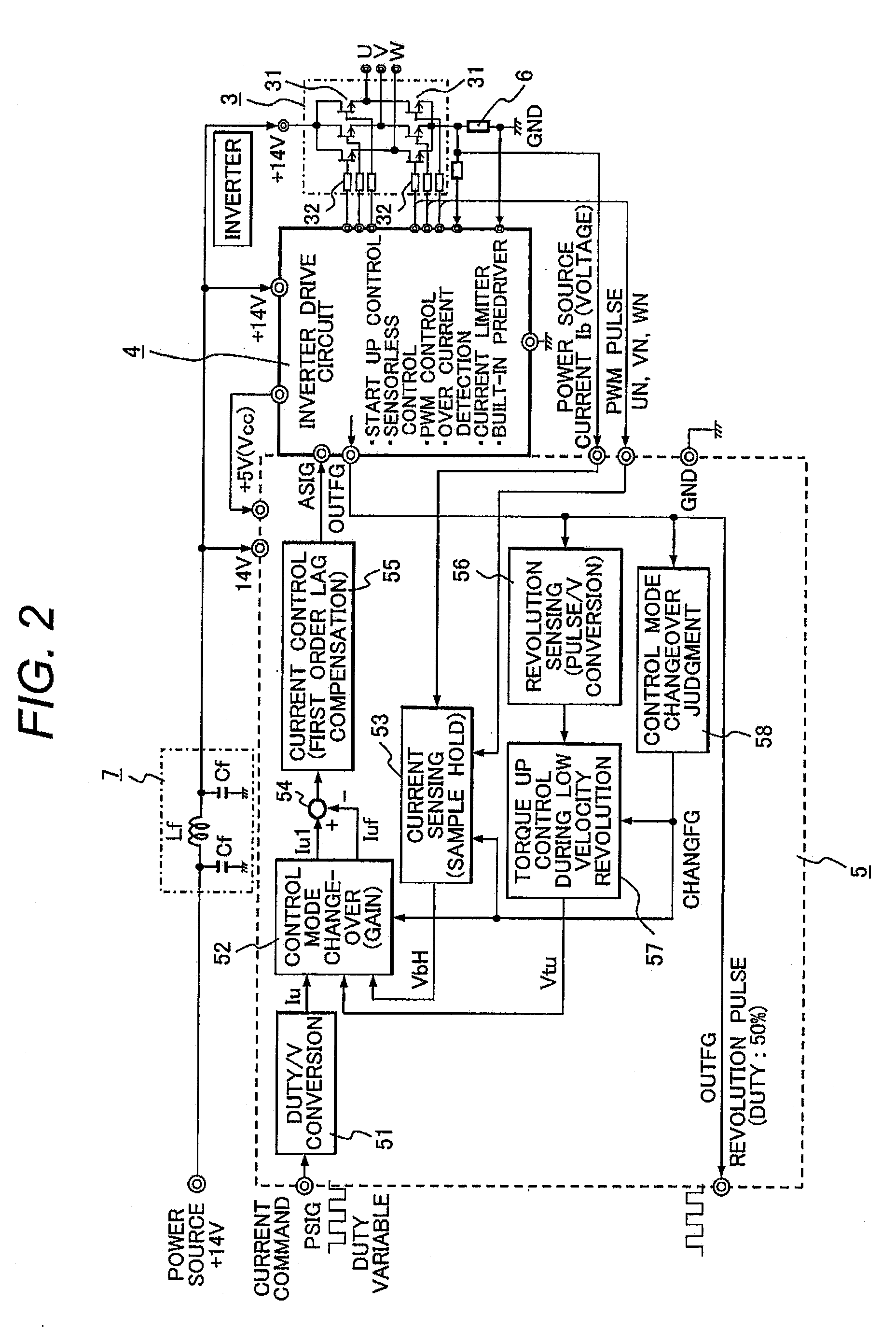
[0033]The torque control part 5 receives a current command in a form of PWM control signal (or an analogue signal) from a superior control device (not illustra...
second embodiment
[0099]The motor control device of the present embodiment is different from the first embodiment on the following point that integrates the above-mentioned control mode changeover part 52, current difference calculating part 54 and current control part 55 in FIG. 4, and comprises the current control part 59 with a circuit constitution different from that of FIG. 4.
[0100]FIG. 12 is a circuit diagram showing constitutions of a control mode changeover part and a current control part (including a current difference calculating part) in a motor control device according to a second embodiment. As shown in FIG. 12, the current control part 59 includes an operational amplifier 591, and the operational amplifier 591 inputs a current command Iu (voltage: e1) in an analogue input signal, a current feed back signal VbH (voltage: e3) and a motor current increase command signal Vtu (voltage e2) to thereby output an analogue signal ASIG (voltage: ez).
[0101]The inputs of the operational amplifier 59...
third embodiment
[0105]The motor control device of the present embodiment is different from the first embodiment on the following point that the above mentioned Duty / V conversion part 51 in FIG. 2 is constituted by a digital circuit.
[0106]FIG. 13 is a circuit diagram of the Duty / V conversion part constituted by a digital circuit. As shown in FIG. 13, a duty / V conversion part 60 of the present embodiment comprises a U / D (up and down) counter 601, a latch circuit 602 that latches a count value of the U / D counter 601, a D / A converter 603 that converts the latched digital data into an analogue value, D type flip flop circuits (herein below, will be called as D-FF circuit) 604 and 605 that are inputted of PWM pulses of the current command PSIG from a superior control device and output counter input pulses to the U / D counter 601, a NAND circuit 606 that adds the output of the D-FF circuits 604 and 605, and a clock generating circuit 607 that feeds clocks to the D-FF circuits 604 and 605.
[0107]An operation...
PUM
 Abstract
Description
Claims
Application Information
 - R&D
- Intellectual Property
- Life Sciences
- Materials
- Tech Scout
- Unparalleled Data Quality
- Higher Quality Content
- 60% Fewer Hallucinations
Browse by: Latest US Patents, China's latest patents, Technical Efficacy Thesaurus, Application Domain, Technology Topic, Popular Technical Reports.
© 2025 PatSnap. All rights reserved.Legal|Privacy policy|Modern Slavery Act Transparency Statement|Sitemap|About US| Contact US: help@patsnap.com