Stripline filter

a filter and stripline technology, applied in the field of stripline filters, can solve the problems of limited expansion of bands, limited stripline line lengths, and difficulty in optionally setting attenuation poles, etc., and achieves the effects of simple process, enhanced jump coupling amount, and stabilized frequency characteristics

Active Publication Date: 2010-09-30
MURATA MFG CO LTD
View PDF5 Cites 3 Cited by
  • Summary
  • Abstract
  • Description
  • Claims
  • Application Information

AI Technical Summary

Benefits of technology

[0014]It is preferred that at least one of the side surface lines is separated from the plurality of resonant lines and an electrode shape on each side surface is the same as an electrode shape on a side surface opposed thereto. This is because, when forming the side electrodes, there is no need to control the orientation of the substrate, and the stripline filter can be configured by a simple process.
[0015]The stripline filter may include an electrode that is connected to the side surface line separated from the plurality of the resonant lines, located on a top surface of the dielectric substrate, and is separated from the plurality of the resonant lines. Even when there are positional errors when cutting the dielectric substrate in the manufacturing process, the interval between this electrode and the resonant line is stabilized, and hence the frequency characteristics can be stabilized.
[0016]The stripline filter may include a capacitance addition electrode that generates a capacitance between the capacitance addition electrode and the second resonant line and generates a capacitance between the capacitance addition electrode and the third resonant line. Thus, the amount of the jump coupling can be enhanced.
[0017]The electrodes on the top surface of the dielectric substrate may be photosensitive electrodes, and the electrodes on a bottom surface and side surfaces of the dielectric substrate may be non-photosensitive electrodes. Thus, the cost of the process for forming the ground electrode and the side surface lines can be reduced while the resonant lines that have a great effect on the filter characteristics are formed with high accuracy.

Problems solved by technology

However, in existing stripline filters, due to constraints on element size and the like, there are limitations on the line lengths of striplines and the degree of coupling between resonators, and there is also a limitation on expansion of bands.
Moreover, it is difficult to optionally set an attenuation pole and the like while achieving wide-band frequency characteristics.
Particularly, it is difficult to provide an attenuation pole on a high frequency side of the band and to finely set its pole frequency.

Method used


Image

  • Stripline filter
  • Stripline filter
  • Stripline filter

Examples


Embodiment Construction

[0048]The following will describe examples of a configuration of a stripline filter according to an embodiment of the invention.

[0049]The stripline filter shown herein is a band-pass filter. The filter shown herein is used for UWB communication in a high frequency band equal to or higher than 3 GHz.

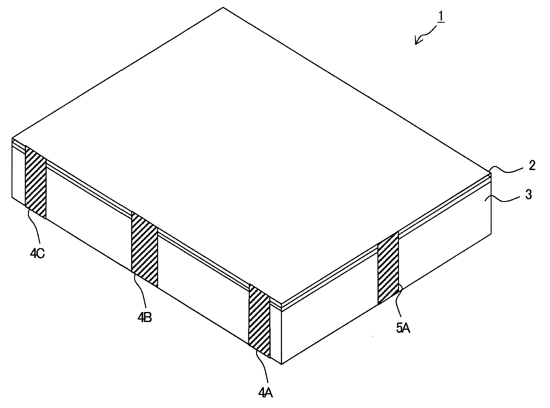
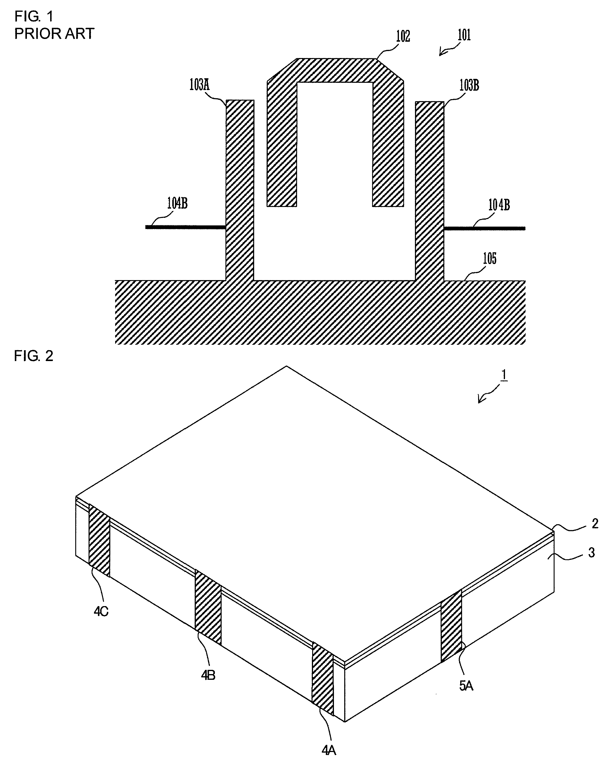
[0050]FIG. 2 is a perspective view of the stripline filter on its top surface side.

[0051]The stripline filter 1 includes a dielectric substrate 3 and a glass layer 2. The substrate 3 is a small rectangular-parallelepiped-shaped, ceramic sintered substrate that is formed from titanium oxide and the like and has a relative dielectric constant of about 111. The composition and the dimension of the substrate 3 are set as appropriate by taking into consideration frequency characteristics and the like. The glass layer 2 is a layer having a thickness of about 15 μm in which a translucent glass and a light blocking glass are laminated, and is laminated on a top surface of the dielectric substrate...


PUM


Abstract

A stripline filter with wide-band filter characteristics having an attenuation pole on a high frequency side of frequency characteristics. The stripline filter includes at least three resonant lines, and two of the resonant lines include parallel line parts and bent parts. The third resonant line has a U shape in which both ends thereof are open and interdigitally coupled to the two resonant lines located on both sides thereof. The parallel line parts extend from base ends connected to a ground electrode via side surface lines that are parallel to respective line parts of the third resonant line. The bent parts extend so as to be bent from ends of the parallel line parts, and face each other at an interval.

Description

CROSS REFERENCE TO RELATED APPLICATIONS [0001]The present application is a continuation of International Application No. PCT / JP2008 / 072745, filed Dec. 15, 2008, which claims priority to Japanese Patent Application No. JP2008-007580, filed Jan. 17, 2008, the entire contents of each of these applications being incorporated herein by reference in their entirety.FIELD OF THE INVENTION [0002]The present invention relates to a stripline filter in which striplines are provided on a dielectric substrate.BACKGROUND OF THE INVENTION[0003]A stripline filter having filter characteristics suitable for a communication system that uses a wide band in a high frequency band, is known (see Patent Document 1).[0004]FIG. 1 shows a configuration of an existing stripline filter. The stripline filter 101 is a filter that uses three resonators. The three resonators are constituted of lines 102, 103A, and 103B, respectively, provided on the same principal surface of a dielectric substrate. The line 102 is b...

Claims


Application Information

Patent Timeline
Patent Type & Authority Applications(United States)
IPC IPC(8): H01P1/203
CPCH01P1/20381H01P1/20327
Inventor MORI, HITOTSUGUHIROSHIMA, MOTOHARU
Owner MURATA MFG CO LTD
Why Eureka
Try Eureka