Techniques for fast area-efficient incremental physical synthesis

a technology of incremental physical synthesis and fast area, applied in the direction of cad circuit design, program control, instruments, etc., can solve the problems of large number of cells, difficult to achieve the effect of physical design without the aid of computers, and complicated connections between cells

Inactive Publication Date: 2010-10-07
GLOBALFOUNDRIES INC
View PDF12 Cites 12 Cited by
  • Summary
  • Abstract
  • Description
  • Claims
  • Application Information

AI Technical Summary

Benefits of technology

[0011]It is therefore one object of the present invention to provide an improved method for physical synthesis of an integrated circuit design.

Problems solved by technology

An IC may include a very large number of cells and require complicated connections between the cells.
Due to the large number of components and the details required by the fabrication process for very large scale integrated (VLSI) devices, physical design is not practical without the aid of computers.
Using a relaxed slew target with EVE can save area but unacceptably sacrifices timing requirements.
However, physical synthesis can take days to complete, and the computational requirements are increasing as designs are ever larger and more gates need to be placed.
There are also more chances for bad placements due to limited area resources.
As process technology scales to the deep-submicron regime (65 nm and smaller), it becomes particularly difficult to achieve timing targets with efficient use of the chip area for model design closure.
This approach has two serious flaws.
First, since area is not a target, the final chip design never has the lowest possible achievable area.
The increased area may lead to congestion problems, or if the chip area is too large the die size will have to be adjusted, introducing additional expense.
Inefficiencies in area also lead to excess power usage.
Second, if area is only considered near the end of the design flow, the process can be stalled in the early optimization stage if there are insufficient space tolerances for buffers or repowering.
Even if some space is available it is unlikely that the optimization result will be the actual optimal solution.

Method used


Image

  • Techniques for fast area-efficient incremental physical synthesis
  • Techniques for fast area-efficient incremental physical synthesis
  • Techniques for fast area-efficient incremental physical synthesis

Examples


Embodiment Construction

)

[0023]With reference now to the figures, and in particular with reference to FIG. 3, there is depicted one embodiment 10 of a computer system in which the present invention may be implemented to carry out the design of logic structures in an integrated circuit. Computer system 10 is a symmetric multiprocessor (SMP) system having a plurality of processors 12a, 12b connected to a system bus 14. System bus 14 is further connected to a combined memory controller / host bridge (MC / HB) 16 which provides an interface to system memory 18. System memory 18 may be a local memory device or alternatively may include a plurality of distributed memory devices, preferably dynamic random-access memory (DRAM). There may be additional structures in the memory hierarchy which are not depicted, such as on-board (L1) and second-level (L2) or third-level (L3) caches.

[0024]MC / HB 16 also has an interface to peripheral component interconnect (PCI) Express links 20a, 20b, 20c. Each PCI Express (PCIe)link 20a,...


PUM


Abstract

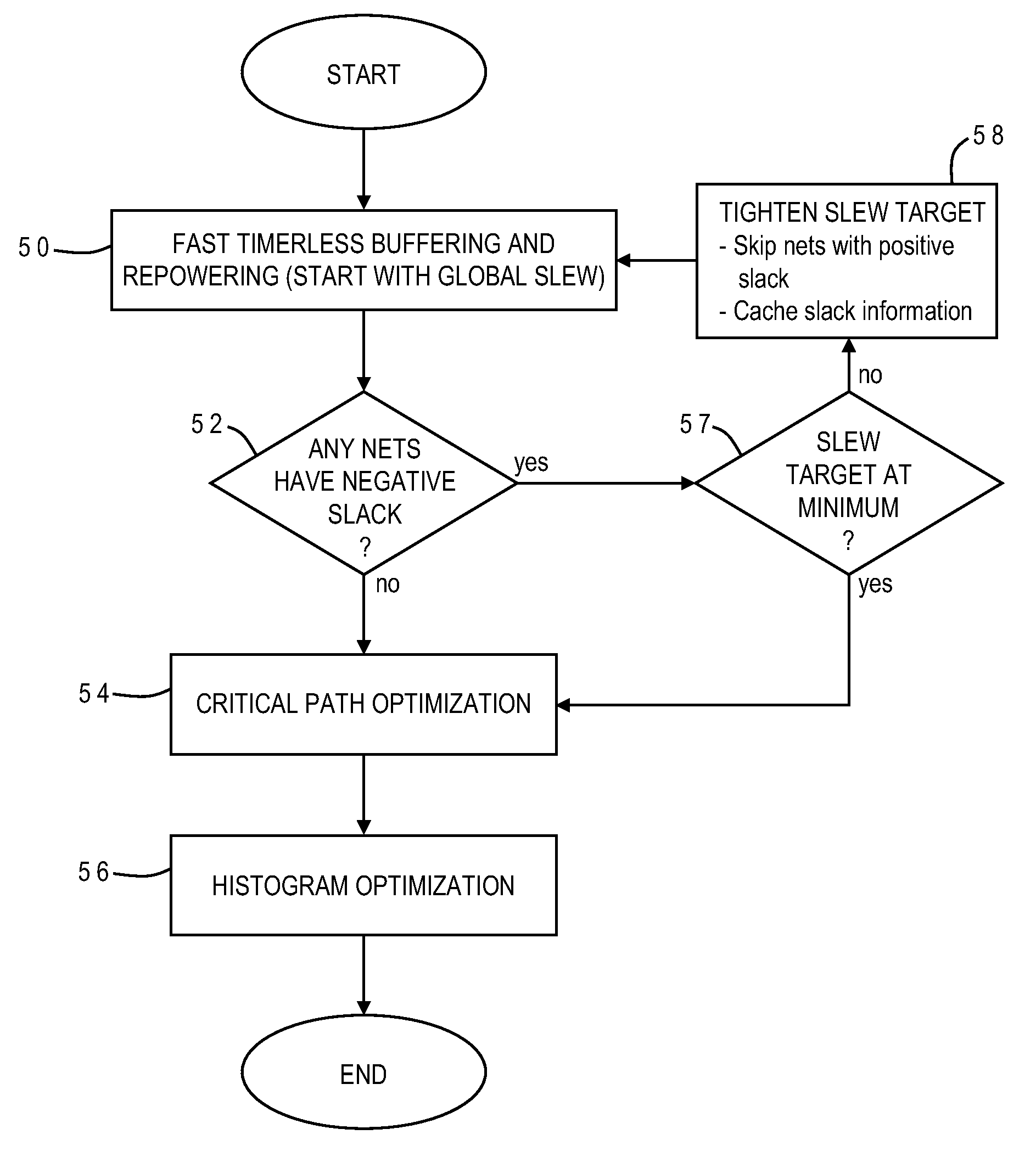
A fast technique for circuit optimization in a physical synthesis flow iteratively repeats slew-driven (timerless) buffering and repowering with a changing slew target. Buffers are added as necessary with each iteration to bring the nets in line with the new slew target, but any nets having positive slack from the previous iteration are skipped, and that slack information is cached for future timing analysis. Buffer insertion is iteratively repeated with incrementally decreasing slew until a minimum slew is reached, or when none of the nets have negative slack. Iteratively repeating the timerless buffering and repowering while gradually decreasing the slew constraint in this manner results in a design structure which retains high quality of results with significantly smaller area and wire length, and with only a small computational overhead.

Description

BACKGROUND OF THE INVENTION[0001]1. Field of the Invention[0002]The present invention generally relates to the design of integrated circuits, and more particularly to a method for physical synthesis of an integrated circuit design using optimization, simulation and analysis tools.[0003]2. Description of the Related Art[0004]Integrated circuits are used for a wide variety of electronic applications, from simple devices such as wristwatches, to the most complex computer systems. A microelectronic integrated circuit (IC) chip can generally be thought of as a collection of logic cells with electrical interconnections between the cells, formed on a semiconductor substrate (e.g., silicon). An IC may include a very large number of cells and require complicated connections between the cells. A cell is a group of one or more circuit elements such as transistors, capacitors, resistors, inductors, and other basic circuit elements grouped to perform a logic function. Cell types include, for exa...

Claims


Application Information

Patent Timeline
Patent Type & Authority Applications(United States)
IPC IPC(8): G06F17/50
CPCG06F17/5068G06F30/39
Inventor ALPERT, CHARLES J.LI, ZHUOSZE, CHIN NGAITREVILLYAN, LOUISE H.ZHOU, YING
Owner GLOBALFOUNDRIES INC
Why Eureka
Try Eureka