
Method of converting a gas tungsten arc welding system to a plasma welding system

Inactive Publication Date: 2010-10-14
CAMARC
View PDF8 Cites 21 Cited by
  • Summary
  • Abstract
  • Description
  • Claims
  • Application Information

AI Technical Summary

Benefits of technology

[0018]In one exemplary embodiment, a plasma torch nozzle assembly includes a shield cup to prevent leakage of a shielding gas, a torch body, an insulator located inside the torch body, an electrode, and an annular ring including focusing holes that focus the shielding gas centrally towards a welding arc.
[0019]In one exemplary embodiment, a plasma torch nozzle assembly includes a shield cup to prevent leakage of a shielding gas, a torch body, an insulator located inside the torch body, an electrode, and a nozzle. The nozzle includes a surface having a central bore and shield gas holes that surround the central bore through which a shielding gas flows that is focused centrally towards a welding arc.

Problems solved by technology

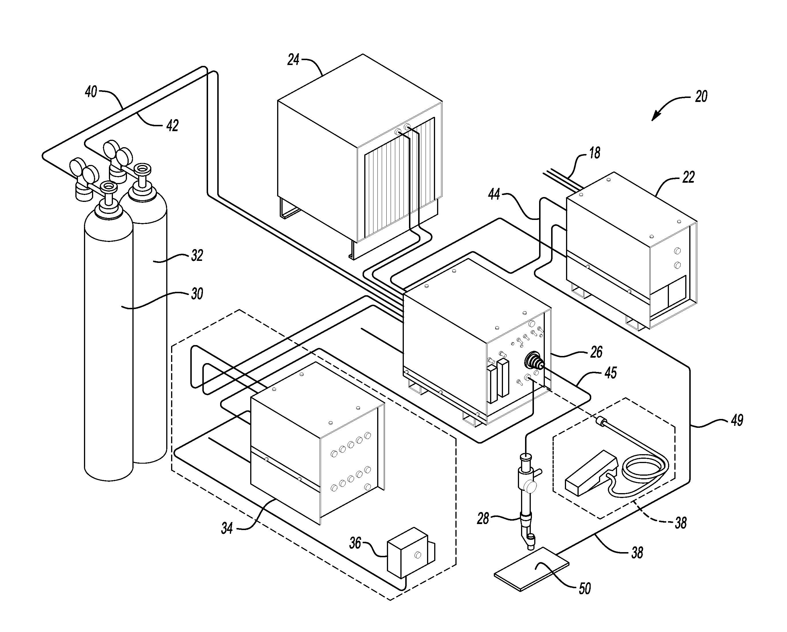
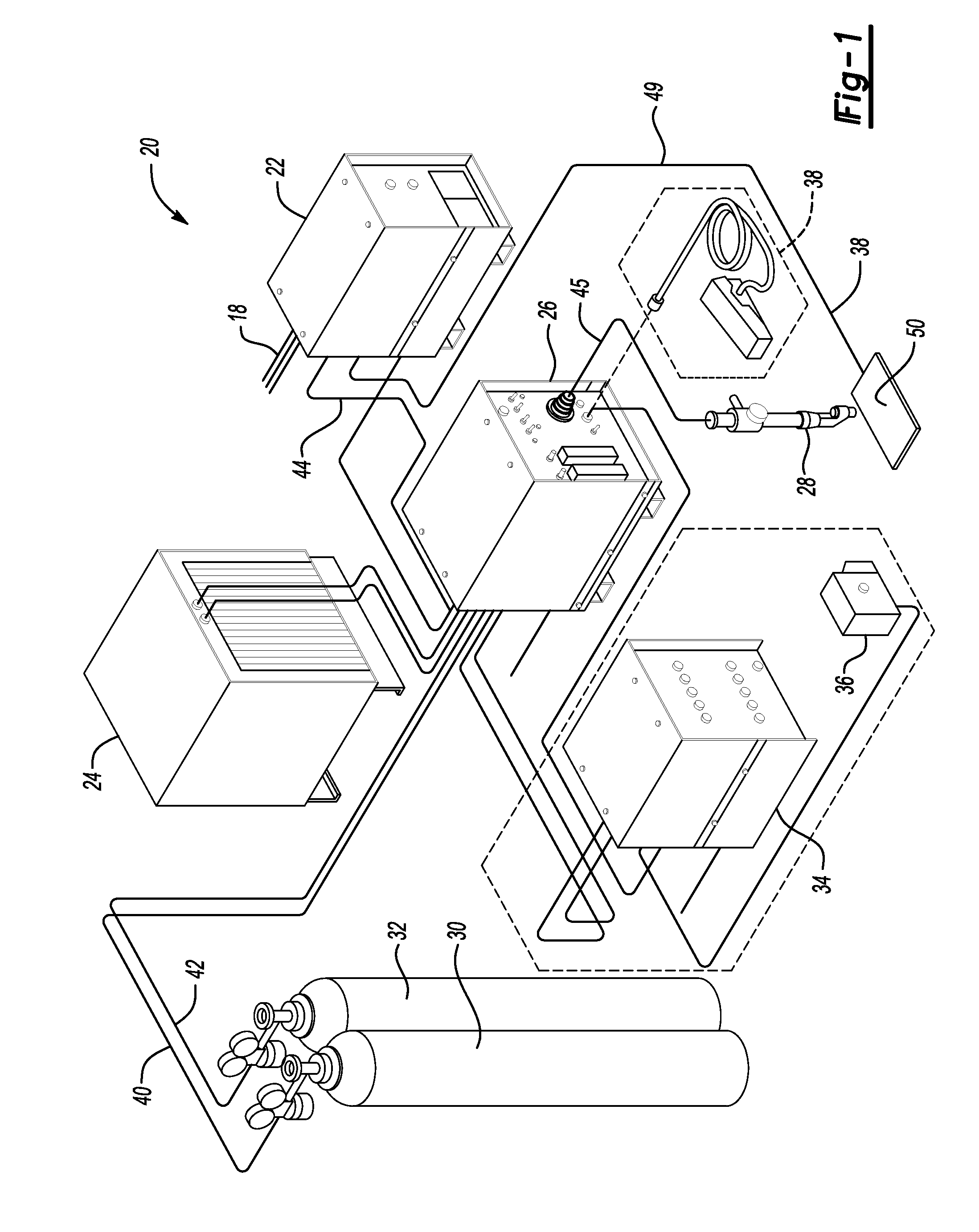
Plasma welding equipment is more expensive than gas tungsten arc welding equipment, at least partially due to the additional cost of a plasma welding control console.
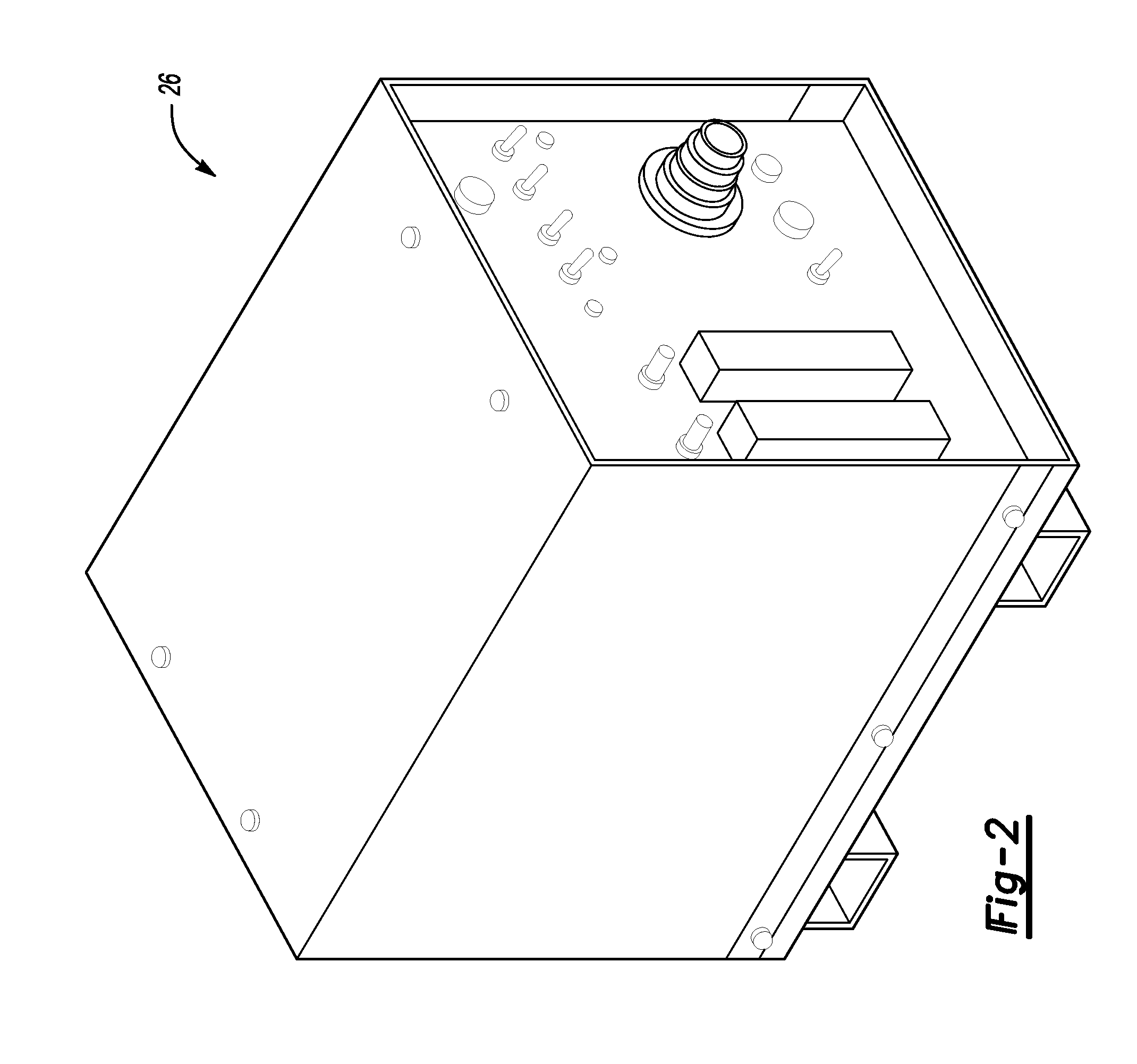
It is expensive to convert a gas tungsten arc welding system to a plasma welding system as the plasma welding control console 26 must be purchased.
The use of a pilot arc can be disadvantageous, particularly in the case of manual welding.
Copper can be difficult to machine, and it can be difficult to drill small holes in this material.

Method used


Image

  • Method of converting a gas tungsten arc welding system to a plasma welding system
  • Method of converting a gas tungsten arc welding system to a plasma welding system
  • Method of converting a gas tungsten arc welding system to a plasma welding system

Examples


Embodiment Construction

[0067]FIG. 5 illustrates the system 58 of the present invention. The system 58 includes a gas console 60 (or a flowmetering “box”) for a plasma gas and a shield gas and a coolant flowswitch 62 connected in series with a remote foot switch pedal 64 (contactor and current control) by a pair of coolant flow switch signal wires 66 connected in series with a power source contactor switch 63 in the remote foot pedal 64 to prevent either accidental or deliberate initiation of a welding arc unless adequate flow of coolant through a plasma welding torch 46 is detected. The gas console 60 includes a plasma gas flowmeter 68 and a shield gas flowmeter 70. A gas tungsten arc welding power source contactor 71 of the gas console 60 functions when an operator presses the remote foot switch pedal 64.

[0068]A supply gas is fed from a regulated source, such as a common gas supply bottle 72, and into a gas tungsten arc welding power source 74 through a hose 102. A solenoid valve (not shown) inside the g...


PUM

PropertyMeasurementUnit
Lengthaaaaaaaaaa
Poweraaaaaaaaaa
Flow rateaaaaaaaaaa

Abstract

A welding system includes a gas tungsten arc welding power source having a welding arc contactor, a plasma welding torch, and a gas console that supplies gases to the plasma welding torch. The welding system also includes a coolant flow switch connected in series with the welding arc contactor. Power is not provided from the gas tungsten arc welding power source to the plasma welding torch when the coolant flow switch is not actuated.

Description

REFERENCE TO RELATED APPLICATION[0001]This application claims priority to U.S. Provisional Application No. 61 / 167,630 filed Apr. 8, 2009.BACKGROUND OF THE INVENTION[0002]The present invention relates generally to a method of converting a gas tungsten arc welding (GTAW) system to a plasma welding system.[0003]Plasma welding equipment is more expensive than gas tungsten arc welding equipment, at least partially due to the additional cost of a plasma welding control console. A plasma welding torch is more internally complex than a gas tungsten arc welding torch as it incorporates design features commensurate with operation of a pilot arc. Manual plasma welding is relatively uncommon in the industrial workplace, although it provides the advantages of deeper weld penetration, a more focused welding arc, and reduced operator dexterity requirements compared to gas tungsten arc welding. Plasma welding can also be used to weld aluminum and magnesium, as can gas tungsten arc welding.[0004]FIG...

Claims


Application Information

Patent Timeline
IPC IPC(8): B23K9/16B23K10/00
CPCB23K10/02B23K9/167
Inventor HUGHES, RUSSELL VERNON
Owner CAMARC
Learn More