Welding light metal workpieces by reaction metallurgy

a reaction metal and workpiece technology, applied in the direction of non-electric welding apparatus, welding apparatus, manufacturing tools, etc., can solve the problems of complex joining of light metals such as aluminum alloys or magnesium alloys, short electrode life, and difficulty in spot welding of both alloy types, so as to minimize the distortion of the weld region, and minimize the effect of unwanted deformation

Active Publication Date: 2010-10-14
GM GLOBAL TECH OPERATIONS LLC
View PDF10 Cites 23 Cited by
  • Summary
  • Abstract
  • Description
  • Claims
  • Application Information

AI Technical Summary

Benefits of technology

[0014]This reactive metallurgy practice is very useful for welding workpieces together over substantial surface areas. In accordance with this invention, the method is practiced to manage the dimensions of the welded article and to minimize distortion of the members at the welded interface. This may be of particular concern, for example, when the workpieces are sheet metal alloys having thicknesses of only a few millimeters or less. Such dimensional control is accomplished by controlling the amount of workpiece material consumed by the reactive material and discarded as reaction product as well as controlling the amount of deformation experienced by the workpieces during joining.
[0015]The temperature of the interface is closely controlled in the heating step to form the mobile reaction product while remaining below the solidu...

Problems solved by technology

Joining light metals such as aluminum alloys or magnesium alloys is complicated by the presence of rapidly forming oxide layers as well as their inherent high electrical and thermal conductivity.
Spot welding of both of these alloy types is typically difficult and requires preparation of the workpiece surface, high currents, high forces, and mechanically well-aligned and stab...

Method used


Image

  • Welding light metal workpieces by reaction metallurgy
  • Welding light metal workpieces by reaction metallurgy
  • Welding light metal workpieces by reaction metallurgy

Examples


Embodiment Construction

[0026]In many embodiments of this invention the process may be used to form solid-state welded interfaces between aluminum alloy workpieces or between magnesium alloy workpieces. Examples of aluminum-base alloys are AA5083 (solidus temperature of 574° C.), AA5454 (solidus 602° C.), and AA6061 (solidus 582° C.). Examples of magnesium-base alloys are AZ31 (solidus temperature of 605° C.), AM60 (solidus temperature of 540° C.), and ZK60 (solidus temperature of 520° C.). In other embodiments of the invention an aluminum-coated steel workpiece or a zinc-coated steel workpiece may be welded to an aluminum alloy or magnesium alloy workpiece.

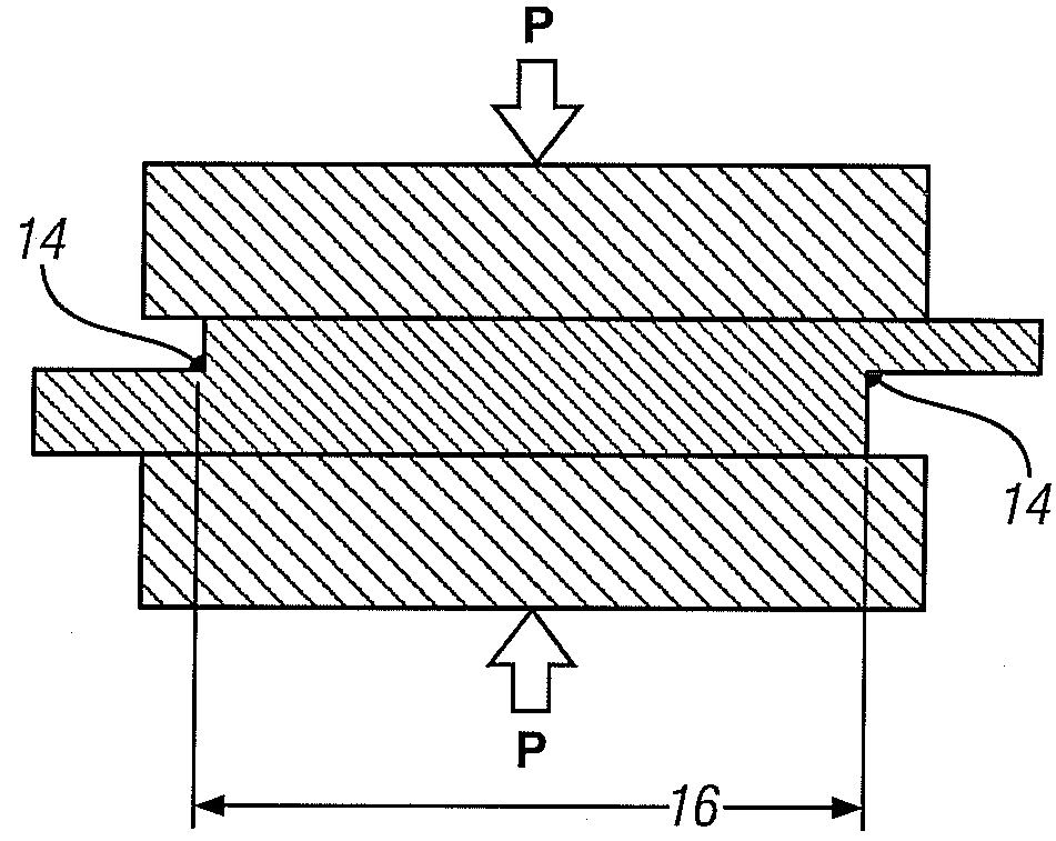
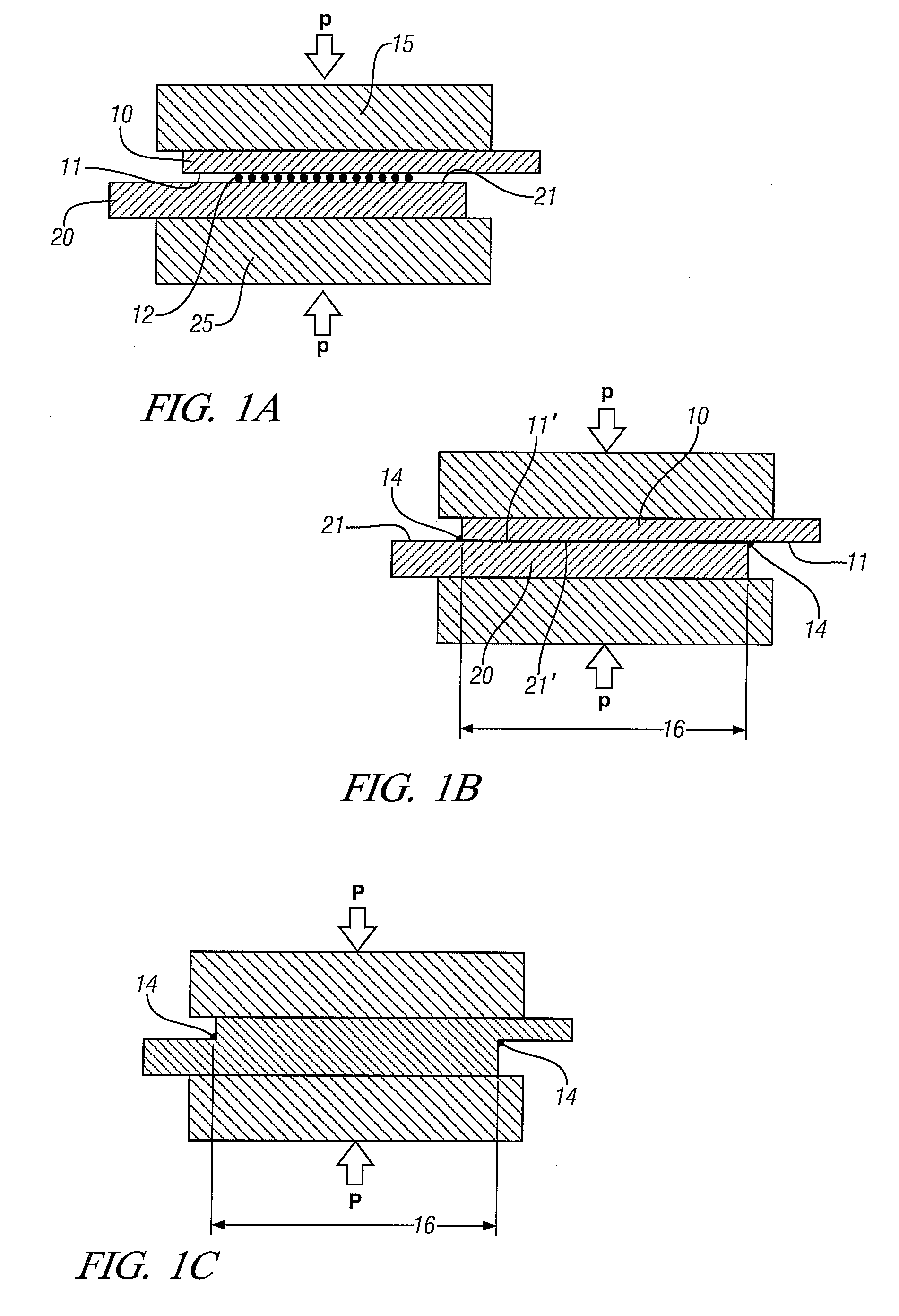
[0027]The process may often be used in welding sheets or other workpieces with relatively thin walls at the joint position. FIGS. 1A-1C are used to illustrate such embodiments.

[0028]In FIG. 1A, two metal workpieces 10 and 20, here shown in an overlapping configuration, are located between two support blocks 15 and 25 respectively with a layer of particu...


PUM

PropertyMeasurementUnit
Lengthaaaaaaaaaa
Fractionaaaaaaaaaa
Thicknessaaaaaaaaaa

Abstract

Aluminum alloy workpieces and/or magnesium alloy workpieces are joined in a solid state weld by use of a reactive material placed, in a suitable form, at the joining surfaces. Joining surfaces of the workpieces are pressed against the interposed reactive material and heated. The reactive material alloys or reacts with the workpiece surfaces consuming some of the surface material in forming a reaction product comprising a low melting liquid that removes oxide films and other surface impediments to a welded bond across the interface. Further pressure is applied to expel the reaction product and to join the workpiece surfaces in a solid state weld bond.

Description

TECHNICAL FIELD[0001]This invention relates to solid-state welding processes for joining workpieces of metal alloys such as aluminum alloys or magnesium alloys. A reaction product comprising a mobile low-melting temperature liquid-containing material is temporarily formed between joining surfaces. The mobile material is formed and used to prepare cleaned, oxide-free aluminum or magnesium surfaces. The cleaned surfaces are then pressed together to expel the reaction product and form a metal-to-metal bond without melting the facing surfaces. The process is practiced to manage consumption and deformation of the facing surfaces of the workpieces.BACKGROUND OF THE INVENTION[0002]Joining light metals such as aluminum alloys or magnesium alloys is complicated by the presence of rapidly forming oxide layers as well as their inherent high electrical and thermal conductivity. Spot welding of both of these alloy types is typically difficult and requires preparation of the workpiece surface, hi...

Claims


Application Information

Patent Timeline
IPC IPC(8): B23K11/18B23K35/34B23K31/02B23K13/01
CPCB23K20/023B23K20/16B23K20/2275B23K20/233B23K2203/20B23K2201/18B23K2203/08B23K2203/10B23K20/2336B23K2101/18B23K2101/34B23K2103/04B23K2103/08B23K2103/10B23K2103/15B23K2103/18B23K2103/20B23K11/11B23K11/163B23K11/20B23K20/10B23K20/2333
Inventor SIGLER, DAVID R.SCHROTH, JAMES G.GAYDEN, XIAOHONG Q.CHEN, YEN-LUNG
Owner GM GLOBAL TECH OPERATIONS LLC
Why Eureka
Try Eureka