
Method of producing welded structure and method of producing battery

Inactive Publication Date: 2010-10-14
TOYOTA JIDOSHA KK
View PDF2 Cites 21 Cited by
  • Summary
  • Abstract
  • Description
  • Claims
  • Application Information

AI Technical Summary

Benefits of technology

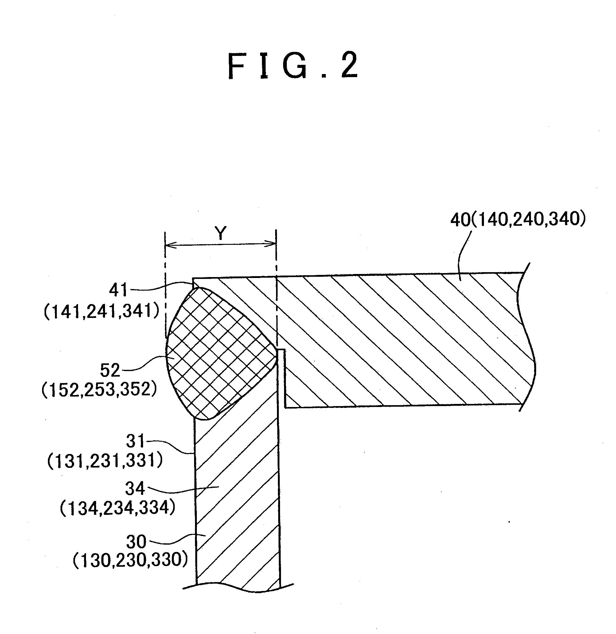
[0011]For example, if a large amount of weld slag is produced during welding, and a part of the metal that forms the cap member and the case body flies off or shatters, the bead thickness is reduced by an amount corresponding to that of the flying metal, and the weld is recessed from the outer surface. According to the method of producing the welded structure as described above, the protrusion can make up for the amount of the metal that flies off as the weld slag (namely, a part of the metal that forms the protrusion flies off as a weld slag), and therefore, the bead thickness can be made larger than that achieved by the conventional method. Consequently, the welding strength is enhanced.
[0016]In the method of producing the welded structure as described above, too, the metal that forms the protrusion makes up for the amount of metal that is reduced by filling the clearance during welding. Therefore, the bead thickness is prevented from being reduced, and is made larger than the bead thickness achieved by the conventional method, so that the first member and the second member can be firmly welded to each other.
[0018]According to the method of producing the battery as described above, the case body and the cap member have the protrusion consisting of at least one of the first protrusion that protrudes from the first outer surface of the case body and the second protrusion that protrudes from the second outer surface of the cap member when the opening of the case body is closed with the cap member. With the protrusion positioned between the first outer surface and the second outer surface, the case body and the cap member are welded together. More specifically, while the electrode assembly is housed in the interior of the case body, and the opening of the case body is closed with the cap member, the protrusion is irradiated with an energy beam, and the case body and the cap member are welded together such that the protrusion provides a part of the weld. Thus, the above-described method makes it possible to produce a battery in which the case body and the cap member are firmly welded together. Consequently, the battery (case) is prevented from being broken or damaged due to an increase in the pressure in the battery.
[0021]If the first protrusion of the case body and the second protrusion of the cap member are too small, the weld bead may not have a sufficiently large thickness, and the case body and the cap member may not be sufficiently firmly welded together. On the contrary, if the first protrusion and the second protrusion are too big, it may be difficult to adequately fuse the opening end portion of the case body and the peripheral portion of the cap member, and the welding strength may be reduced.

Problems solved by technology

Therefore, the resulting battery (welded structure) may not be sufficiently resistant to pressure, namely, may not achieve a sufficiently high withstand pressure.
In these cases, a battery (welded structure) in which the case body (first member) and the cap member (second member) are sufficiently firmly welded together cannot be provided.

Method used


Image

  • Method of producing welded structure and method of producing battery
  • Method of producing welded structure and method of producing battery
  • Method of producing welded structure and method of producing battery

Examples


Embodiment Construction

[0041]Example embodiments of the present invention will be described in greater detail below with reference to the accompanying drawings.

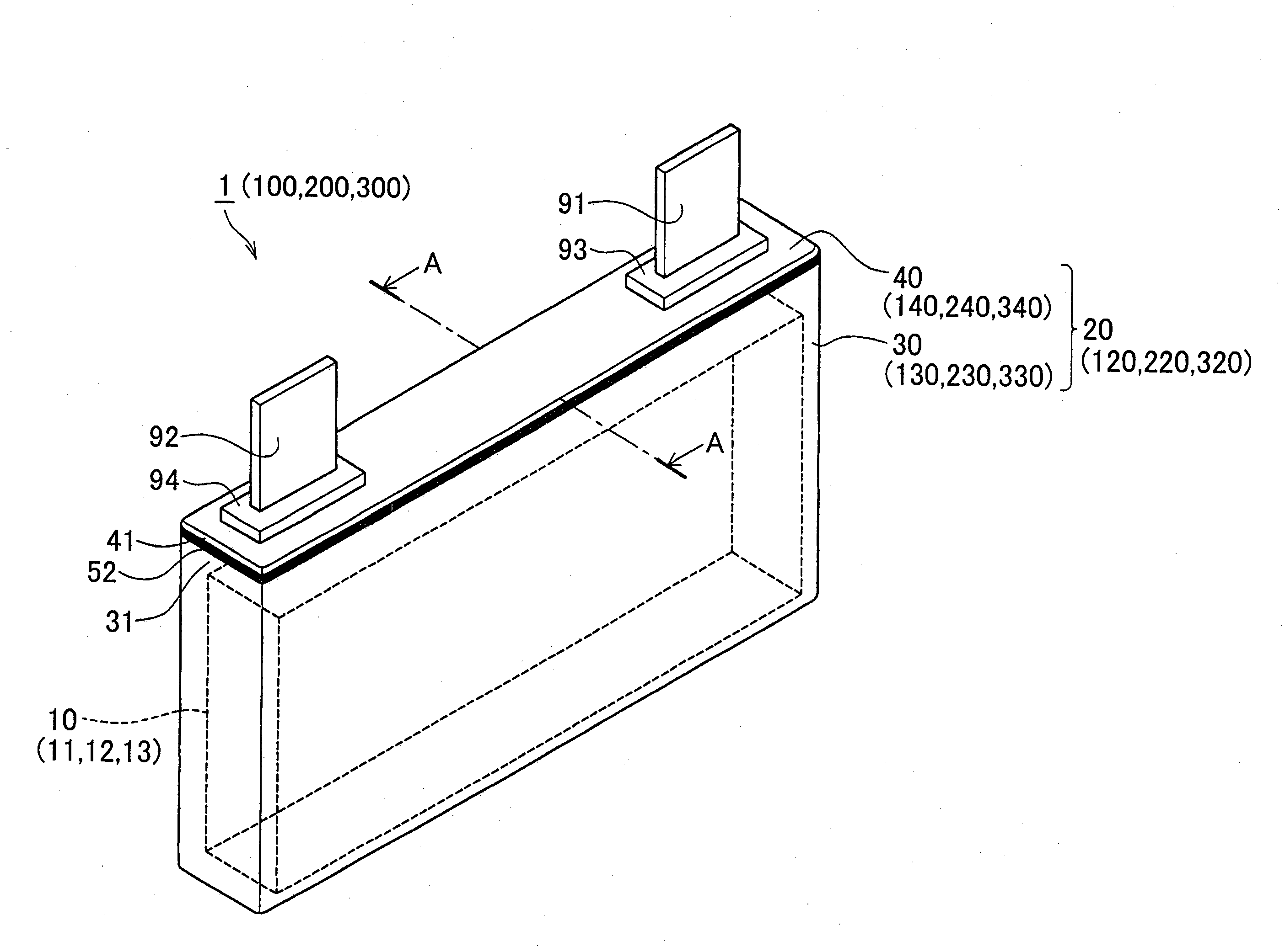
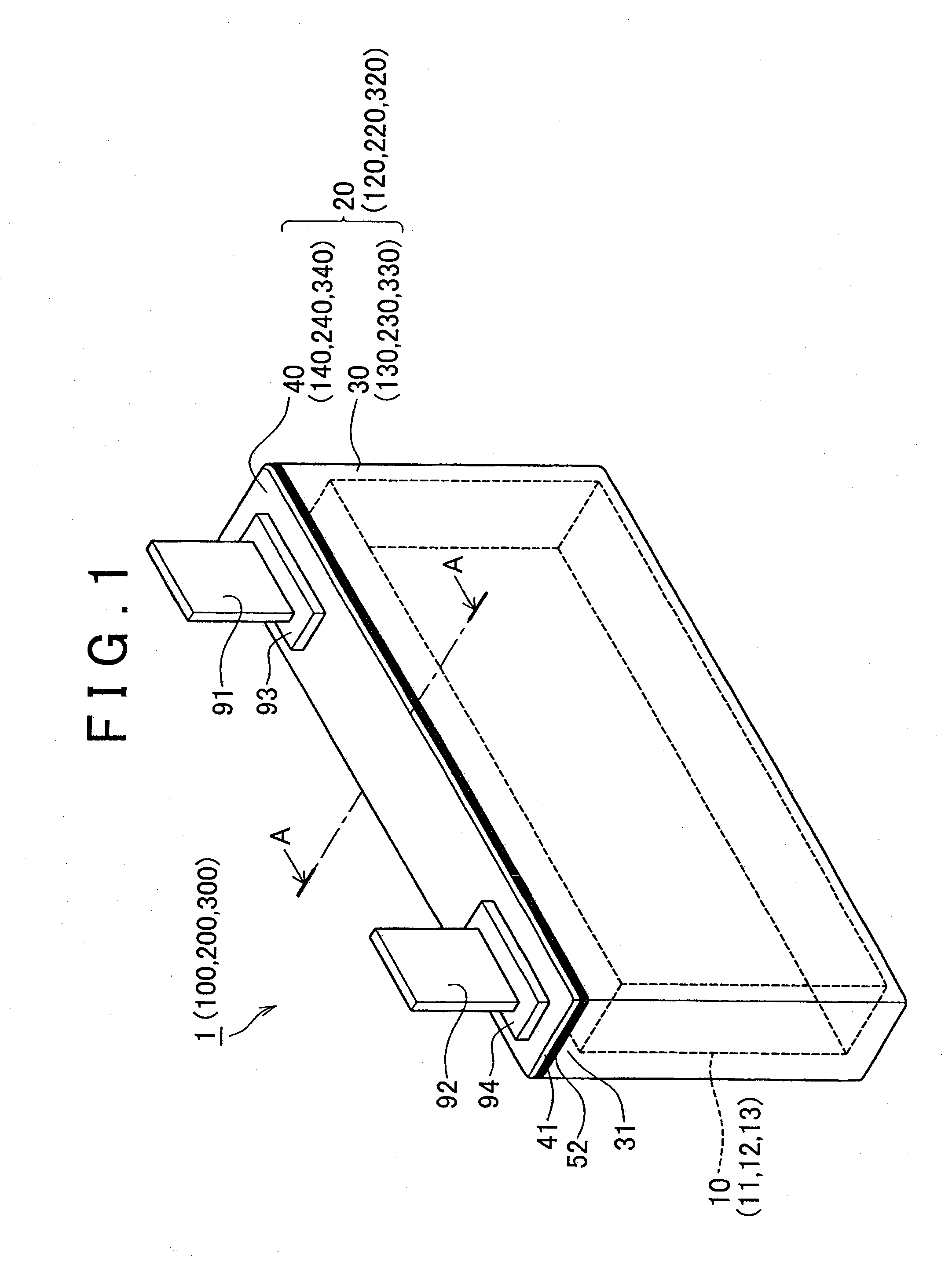
[0042]Referring to FIG. 1 through FIG. 17, first through fifth embodiments of the invention will be described. As shown in FIG. 1, a battery 1 of the first embodiment is a box-type, sealed lithium-ion secondary battery shaped like a rectangular parallelepiped. The battery 1 has an electrode assembly 10, a battery case 20 that houses the electrode assembly 10, a positive terminal 91, and a negative terminal 92. The battery 1 is used as, for example, a power supply for driving an electric vehicle or a hybrid car.

[0043]The electrode assembly 10 is a flat, rolled structure formed by rolling sheet-like positive-electrode plate 11, negative-electrode plate 12 and separator 13 together. The electrode assembly 10 includes a positive-electrode rolled section in which only a part of the positive-electrode plate 11 is folded into a roll, and a negative-electr...


PUM

PropertyMeasurementUnit
Ratioaaaaaaaaaa

Abstract

A case body (a first member) and a cap member (a second member) that have not been subjected to welding include a protrusion consisting of at least one of a first protrusion that protrudes from a first outer surface and a second protrusion that protrudes from a second outer surface when the case body and the cap member are assembled together such that the first outer surface is flush with the second outer surface. The protrusion is placed between the first outer surface and the second outer surface. In a condition where the first outer surface and second outer surface of the pre-welding case body and cap member are flush with each other, and the protrusion is placed between the first outer surface and the second outer surface, the protrusion is irradiated with a laser beam, so that the case body and the cap member are welded together with the protrusion providing a part of a weld. Thus, a method of producing a welded structure is provided for producing a welded structure in which the first member and the second member are firmly welded together.

Description

BACKGROUND OF THE INVENTION[0001]1. Field of the Invention[0002]The invention relates to a method of producing a welded structure, and a method of producing a battery.[0003]2. Description of the Related Art[0004]In recent years, various types of batteries have been proposed which are used as power supplies of portable equipment and cellular telephones, or used as power supplies of electric vehicles and hybrid cars. One type of the batteries has an electrode assembly, a case body in which the electrode assembly is housed, and a cap member that closes the opening of the case body, and the case body and the cap member are welded together (as disclosed in, for example, Japanese Patent Application Publication No. 2002-184365 (JP-A-2002-184365) and Japanese Patent Application Publication No. 11-77347 (JP-A-11-77347)).[0005]Japanese Patent Application Publication No. 2002-184365 (JP-A-2002-184365) discloses a method of sealing an opening of a sealed-type battery having an electrode assembl...

Claims


Application Information

Patent Timeline
IPC IPC(8): B23K15/00B23K26/00B23K26/21H01M2/02B23K101/12B23K101/36H01M2/04
CPCB23K26/02B23K2101/36H01M50/10H01M50/147
Inventor SUZUKI, SATOSHIITO, KATSUMI
Owner TOYOTA JIDOSHA KK
Learn More