Biological desulfurization apparatus

a technology of desulfurization apparatus and desulfurization chamber, which is applied in the direction of gaseous fuels, biomass after-treatment, separation processes, etc., can solve the problems of corroding facilities, easy clogging of the packed layer with microorganisms, and rocketing running costs, and achieves stable treatment

Inactive Publication Date: 2010-10-14
KK TOSHIBA
View PDF1 Cites 11 Cited by
  • Summary
  • Abstract
  • Description
  • Claims
  • Application Information

AI Technical Summary

Benefits of technology

[0011]According to the present invention, there can be provided a biological desulfurization apparatus for biogas, which can prevent clogging in the carrier-packed layer and can hold microorganisms adhering to the carrier, thereby enabling stable treatment.

Problems solved by technology

This is because the hydrogen sulfide gas in biogas is oxidized upon combustion of biogas, and forms sulfur oxide which can in turn corrode facilities.
However, these methods are used in a system where running costs are rocketed because chemicals such as an adsorbent are required for adsorption and the adsorbent after adsorption turns to waste.
In this desulfurization technique, there has been pointed out a problem that a packed layer is easily clogged with microorganisms multiplied at the bottom of the packed layer or on a supporting part of the packed layer or with a sulfur component formed by oxidization of the removed hydrogen sulfide.
However, when a sulfur component deposited in the packed layer is removed by washing with water, the microorganisms may also be washed away together with a sulfur component.
That is, when the washing time is short, a sulfur component cannot be sufficiently removed, thus easily permitting clogging.
On the other hand, when the washing time is long, a sufficient amount of microorganisms necessary for removal of hydrogen sulfide cannot be secured, so there arises a problem that the ability to remove hydrogen sulfide is reduced after washing.
During washing, the carrier is allowed to float in water, thus increasing the efficiency of washing, but because the supporting plate for the carrier is fixed, its adhering matter is not sufficiently removed by washing and may allow the carrier supporting plate to be clogged to cause a problem of reduction in treatment efficiency.
Accordingly, when the amount of mixed air is small, there occurs the case where microorganisms in the upper part of the packed layer cannot sufficiently flourish.

Method used


Image

  • Biological desulfurization apparatus
  • Biological desulfurization apparatus
  • Biological desulfurization apparatus

Examples


example 1

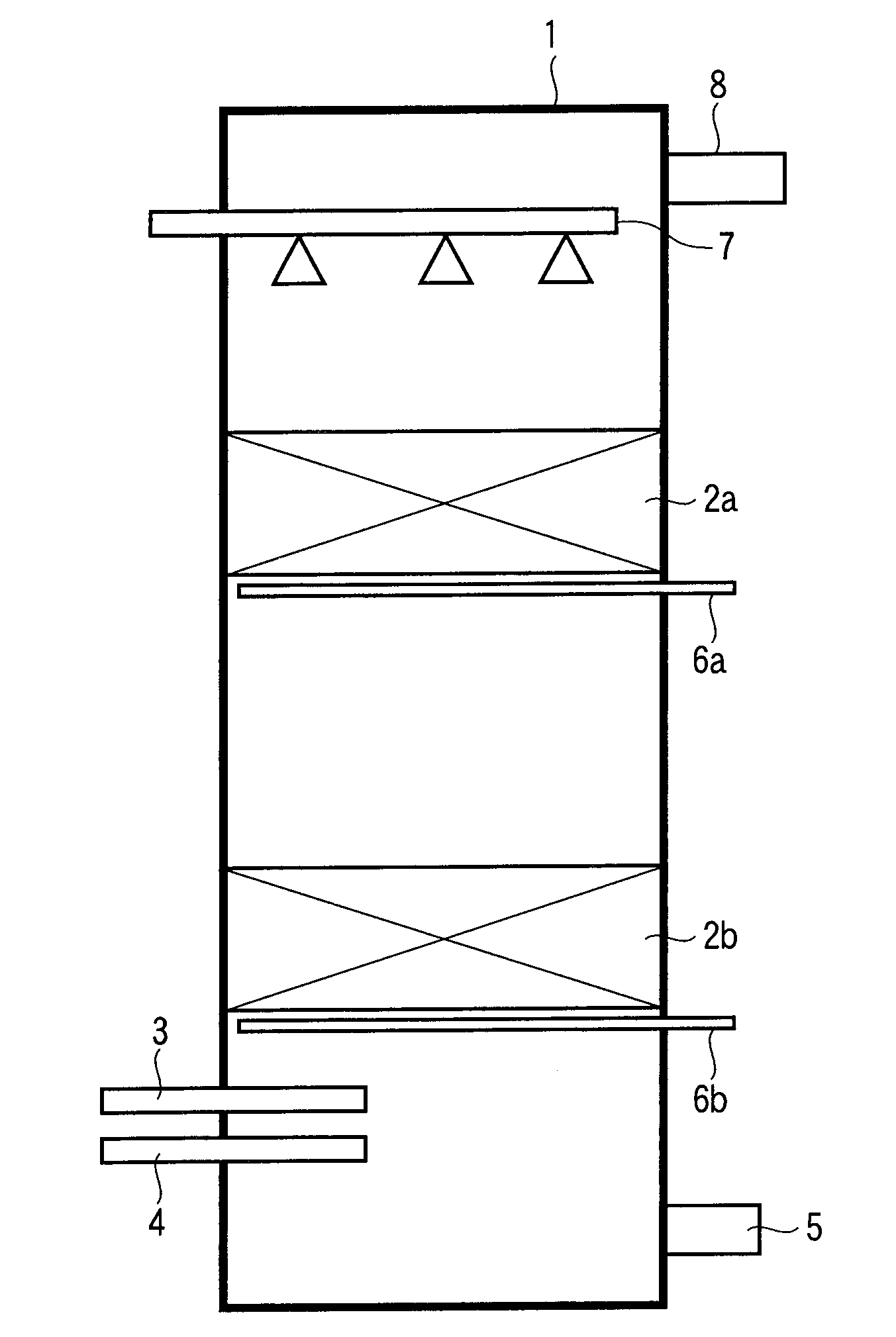
[0056]For the biological desulfurization apparatus for biogas in Example 1, FIG. 1 is referred to. Numeral 1 in the figure is a reaction tower (biological reaction tank) into which biogas generated by anaerobically fermenting organic waste is introduced. Upper-stage packed layer 2a and lower-stage packed layer 2b provided respectively with a carrier to which microorganisms had adhered are arranged vertically in the reaction tower 1. The diameter of the carrier constituting the lower-stage packed layer 2b is set greater than the diameter of the carrier constituting the upper-stage packed layer 2a. An air feeding pipe for feeding air (air feeder) 3, a biogas feeding pipe 4 for feeding biogas to the reaction tower 1, and a drain tube 5 for discharging water supplied to the reaction tower 1 are arranged respectively below the lower-stage packed layer 2b in the reaction tower 1. Washing air pipes 6a and 6b are arranged below the upper-stage packed layer 2a and lower-stage packed layer 2b...

example 2

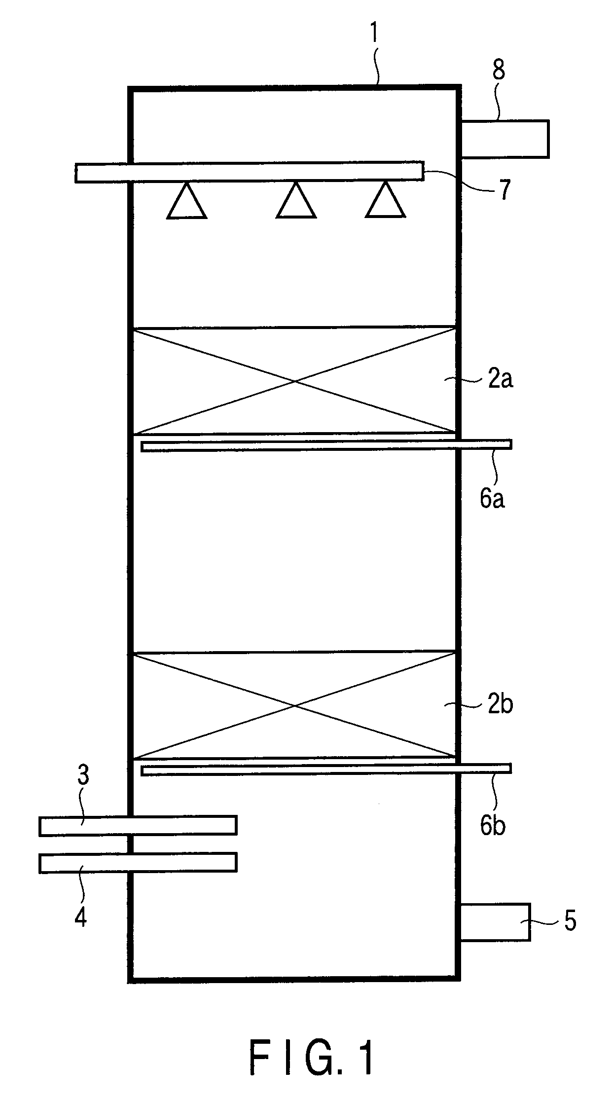
[0061]For the biological desulfurization apparatus for biogas in Example 2, FIG. 2 is referred to. The same members as in FIG. 1 are assigned like numerals to omit their description, and the main part only is described.

[0062]Numeral 11 in the figure is an intermediate sprinkling mechanism (sprinkling nozzle) arranged to face upward in the reaction tower 1 between the upper-stage packed layer 2a and lower-stage packed layer 2b.

[0063]In the biological desulfurization apparatus for biogas in FIG. 2, it is possible to feed water not only from the sprinkling mechanism 7 arranged in an upper part of the reaction tower 1, but also from the intermediate sprinkling mechanism 11. As described in Example 1, hydrogen sulfide gas contained in biogas flowing from the biogas feeding pipe 4 in the lower part of the reaction tower 1 is oxidized by microorganisms adhering to the surfaces of the upper-stage packed layer 2a and lower-stage packed layer 2b and thereby precipitated as a sulfur component...

example 3

[0068]For the biological desulfurization apparatus for biogas in Example 3, FIG. 3 is referred to. The same members as in FIGS. 1 and 2 are assigned like numerals to omit their description, and the main part only is described.

[0069]Numeral 12 in the figure is an intermediate air feeding pipe (hollow air feeder) for feeding air arranged between the upper-stage packed layer 2a and lower-stage packed layer 2b.

[0070]In the biological desulfurization apparatus for biogas in FIG. 3, it is possible to feed air not only from an air feeding pipe 3 arranged in the lower part of the reaction tower 1, but also from the intermediate air feeding pipe 12. The microorganisms that have adhered to the surface of the carrier in the upper-stage packed layer 2a and lower-stage packed layer 2b require oxygen for their growth because they are aerobic, sulfur-oxidizing bacteria of the genus Thiobacillus. When the air feeding pipe 3 is present at only the same site as in the biogas inflow portion and the c...


PUM

PropertyMeasurementUnit
timeaaaaaaaaaa
diameteraaaaaaaaaa
frequencyaaaaaaaaaa

Abstract

Disclosed is a biological desulfurization apparatus including a reaction tower 1 into which biogas generated by anaerobic fermentation of organic waste is to be introduced, a carrier-packed layer 2a, 2b arranged in the reaction tower and provided with a carrier to which microorganisms have adhered, an air feeding pipe 3 that mixes air into a lower part of the reaction tower, and a sprinkling mechanism 7 that sprinkles water on an upper part of the reaction tower, wherein the carrier-packed layer is arranged in two or more stages.

Description

TECHNICAL FIELD[0001]The present invention relates to a biological desulfurization apparatus, and in particular to a biological desulfurization apparatus for biogas generated by anaerobic digestive treatment of organic discharged water such as sewage and industrial drainage.BACKGROUND ART[0002]A methane fermentation process is often used as a method of treating organic waste such as sewage sludge and raw garbage or organic discharged water such as food factory effluent. The methane fermentation process is a treatment process wherein organic discharged water is introduced into a reaction tower and organic matter in the discharged water is decomposed by a group of methane fermentation bacteria packed in a reaction tank, thereby forming biogas consisting primarily of methane gas and simultaneously decomposing and removing the organic matter. However, when sulfur components such as those derived from proteins are contained in discharged water, the sulfur components are reduced by the ac...

Claims


Application Information

Patent Timeline
Patent Type & Authority Applications(United States)
IPC IPC(8): C12M1/107
CPCB01D53/52B01D53/84B01D2251/11B01D2251/95C12M47/18C10L3/08C10L3/10C10L3/102Y02E50/343B01D2258/05Y02E50/30Y02A50/20
Inventor NAGAMORI, YASUHIKOOBARA, TAKUMIASHIKAGA, NOBUYUKITAMURA, HIROSHIISHIGE, TAKAYUKIYAMAMORI, TAKEO
Owner KK TOSHIBA
Why Eureka
Try Eureka