Composite electric wire

a technology of electric wire and composite wire, which is applied in the direction of insulated conductors, cables, conductors, etc., can solve the problems of limited strength of aluminum wire and aluminum wire composed of aluminum element wires or aluminum alloy elements, and is not suitable for in-vehicle environment, so as to improve mechanical strength and reliability, the effect of light weigh

Inactive Publication Date: 2010-10-21
YAZAKI CORP
View PDF3 Cites 41 Cited by
  • Summary
  • Abstract
  • Description
  • Claims
  • Application Information

AI Technical Summary

Benefits of technology

[0029]According to the configuration of (3), because copper included in the copper-coated aluminum element wire composing the outer circumference of the center conductor and copper of the copper element wires are the same copper material, the contact between the copper element wire as the outer-layer conductor and the center conductor is the contact between the complete same metals of copper and copper, and no electrical potential difference is generated at the contact surface, so that the electric erosion is further surely prevented.
[0030]According to the present invention, the composite electric wire is intended to realize a light weight and improve a mechanical strength at the same time. Further, the composite electric wire is enabled to improve the reliability by avoiding the problems of oxide coating and electric erosion so that the electric wire may be easily handled for use as an on-vehicle wire harness.

Problems solved by technology

However, conventional aluminum wire composed of aluminum element wire or aluminum alloy element wire is not suitable for in-vehicle environment.
Namely, in vehicle environment, high strength against bending or pulling of the wire is required because of the necessity of routing the wire in a limited space, however, the aluminum wire having less strength than the copper wire is limited in a range of application of in-vehicle environment in view of environmental resistance (high temperature, high humidity, bending, pulling, or the like).

Method used


Image

  • Composite electric wire
  • Composite electric wire
  • Composite electric wire

Examples


Embodiment Construction

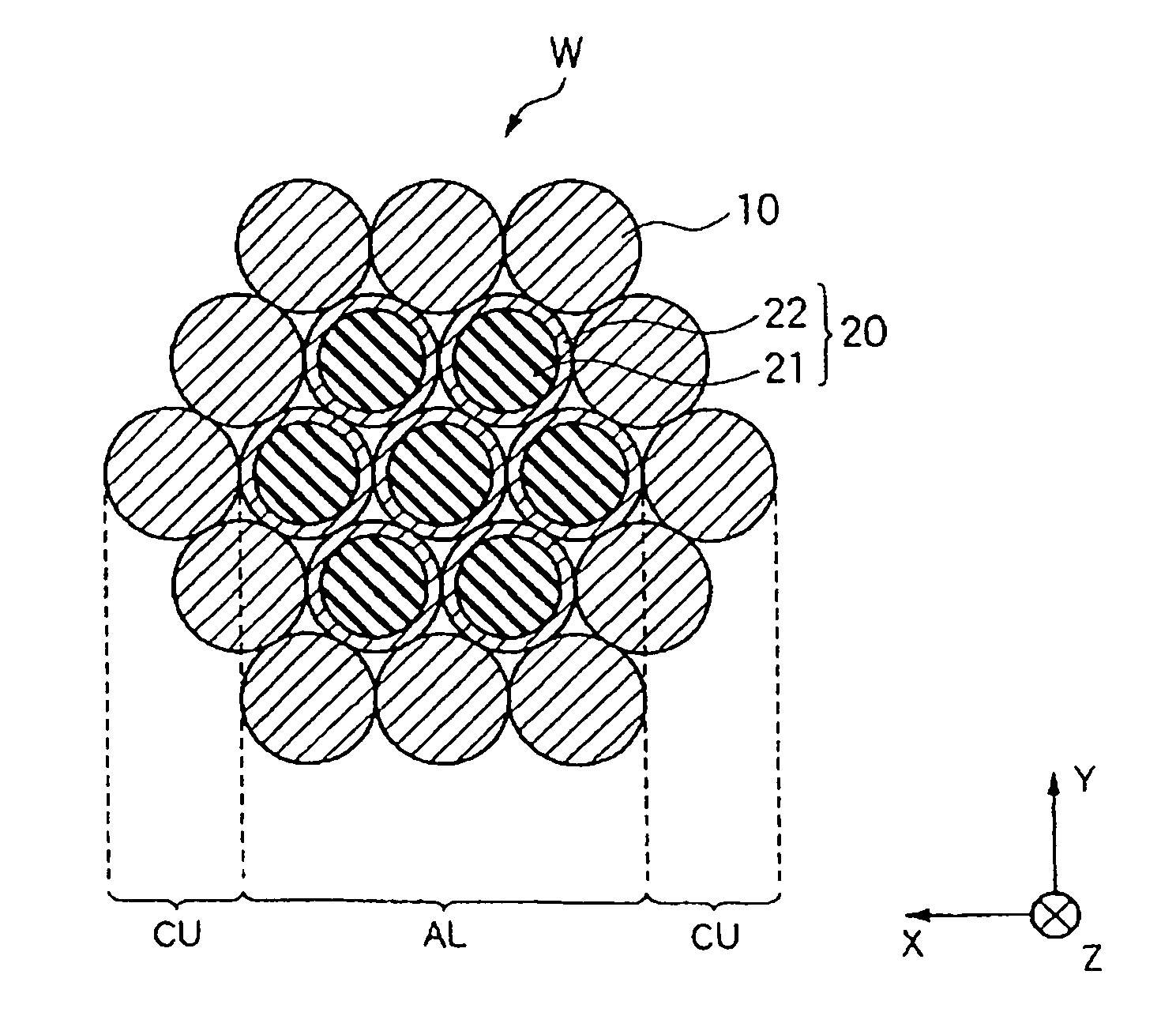
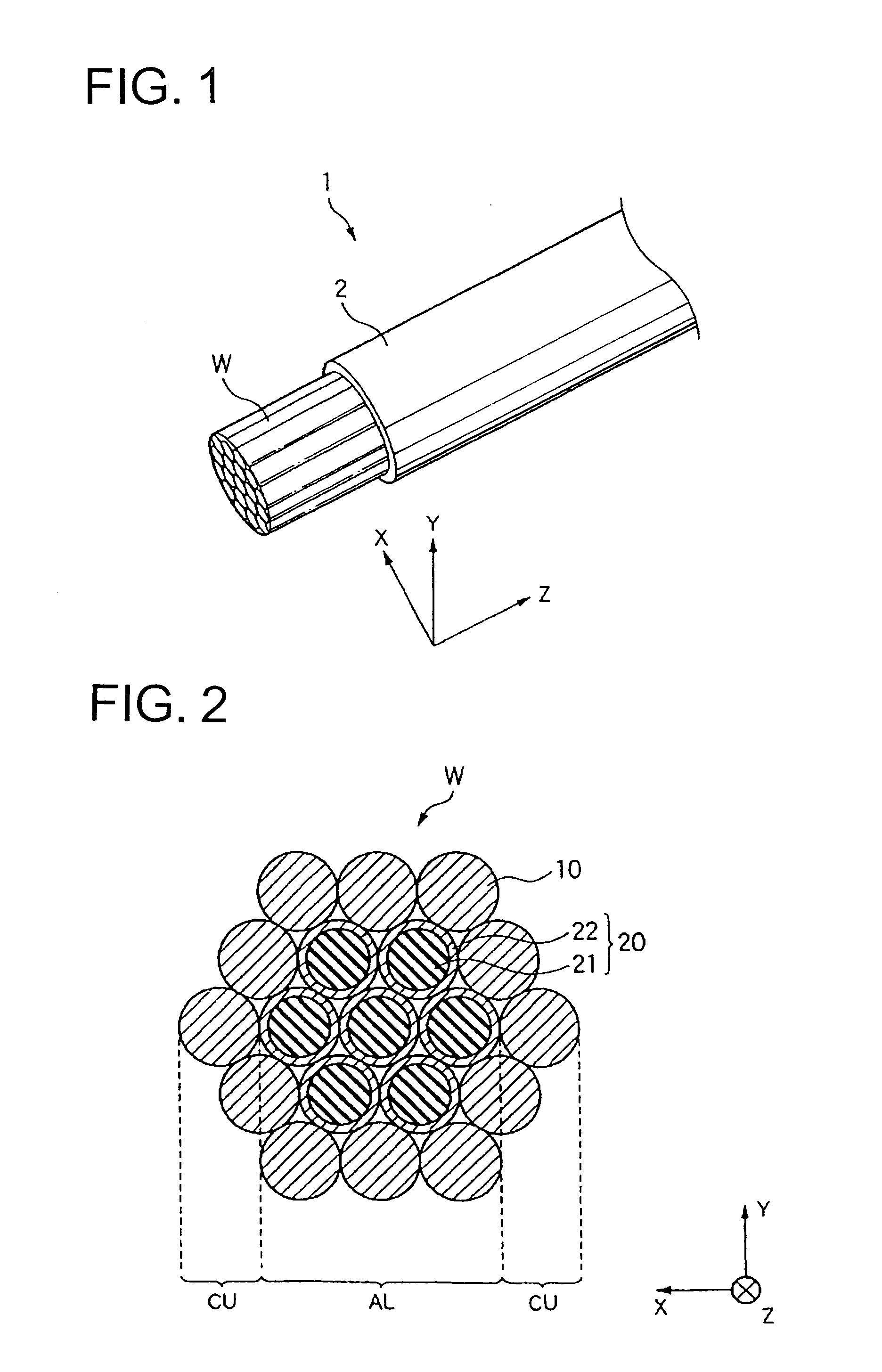
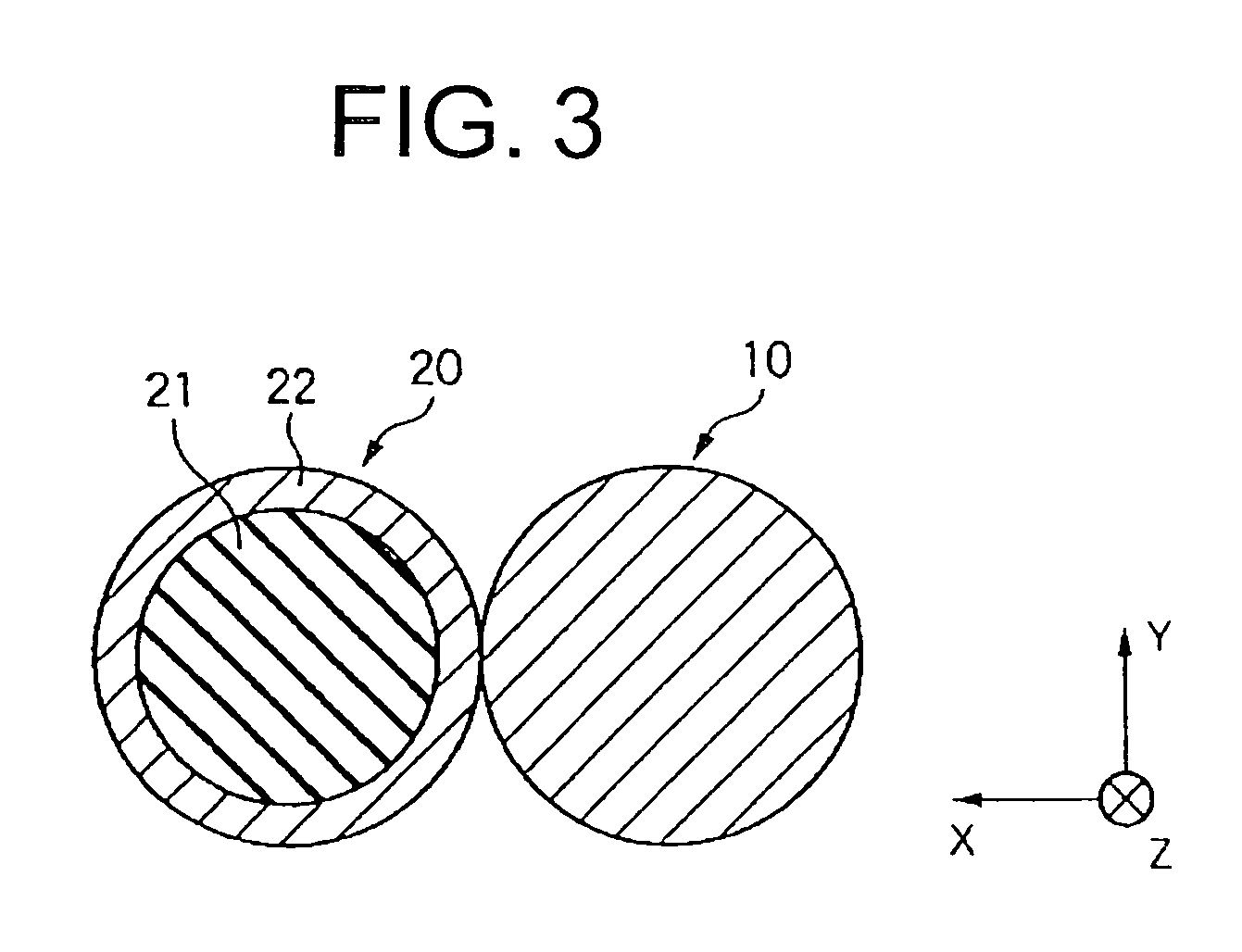
[0041]Hereinafter, a preferred embodiment according to the present invention will be explained with reference to figures. FIG. 1 is a perspective view showing an electric wire according to the embodiment. FIG. 2 is a sectional view showing conductors of the electric wire according to the embodiment. FIG. 3 is an enlarged view showing a contact portion between a copper element wire and a copper-coated aluminum element wire of the electric wire according to the present invention. Incidentally, a longitudinal direction of a composite electric wire (electric wire body) is defined as “Z direction”, and a plane perpendicular to the Z direction, namely, a plane including a section of the electric wire body is defined as “X-Y plane”, and explained below.

[0042]As shown in FIG. 1, a composite electric wire 1 according to this embodiment includes: an electric wire body W composed of center conductors AL and outer-layer conductors CU arranged to extend in the Z direction along the outer circumf...


PUM

PropertyMeasurementUnit
electricaaaaaaaaaa
circumferencesaaaaaaaaaa
circumferenceaaaaaaaaaa

Abstract

Provided is a composite electric wire, which is intended to realize a light weight and improve a mechanical strength at the same time and which is enabled to improve the reliability by avoiding the problem of oxide coating or electric erosion so that the electric wire may be easily handled for use as a car-mounted wire harness.The composite electric wire comprises an electric wire body (W) composed of center conductors (AL) and outer-layer conductors (CU) arranged to extend in a Z-direction along the outer circumferences of the center conductors (AL) and to enclose the center conductors (AL). In the electric wire body (W), the center conductors (AL) composed of copper-coated aluminum element wires (20) of a (1+6) number are sectionally positioned at the center portion of the electric wire body (W) in an X-Y plane, and the outer-layer conductors (CU) composed of twelve copper element wires (10) are positioned in the outer circumference portion arranged around the center portion of the X-Y plane. Moreover, the outer-layer conductors (CU) make contact at their outer circumferences with the outer circumferences of the center conductors (AL), thereby to make their electric connections.

Description

TECHNICAL FIELD[0001]This invention relates to a composite electric wire having different types of element wires arranged at a center portion and at an outer circumference portion, in particular, to a composite electric wire suitable for use as a wire harness to be mounted on a vehicle or the like.BACKGROUND[0002]Conventionally, a copper electric wire is typically used as a wire harness routed in a vehicle or the like because of its good electrical conductivity. However, recently, a demand for replacing the copper electric wire with an aluminum electric wire has been increased in view of low weight, good fuel economy owing to the low weight, and recycle of metal resources in addition to a lack of copper resources, and price increase due to the lack of copper resources.[0003]Because aluminum has high electric conductivity next to copper, and good workability for wire drawing, and is lightweight (specific gravity is one third of that of copper), conventionally, aluminum is used as ele...

Claims


Application Information

Patent Timeline
Patent Type & Authority Applications(United States)
IPC IPC(8): H01B5/08
CPCC23C10/28H01B1/023H01B7/0045H01B7/0009H01B1/026
Inventor WATANABE, JIN
Owner YAZAKI CORP
Why Eureka
Try Eureka