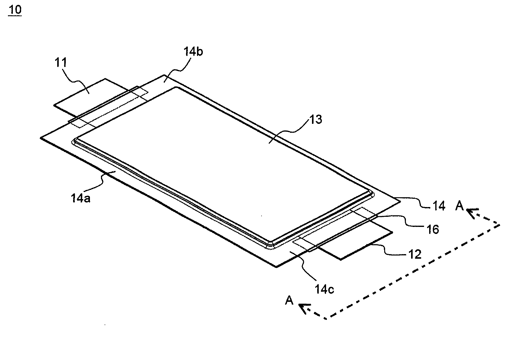
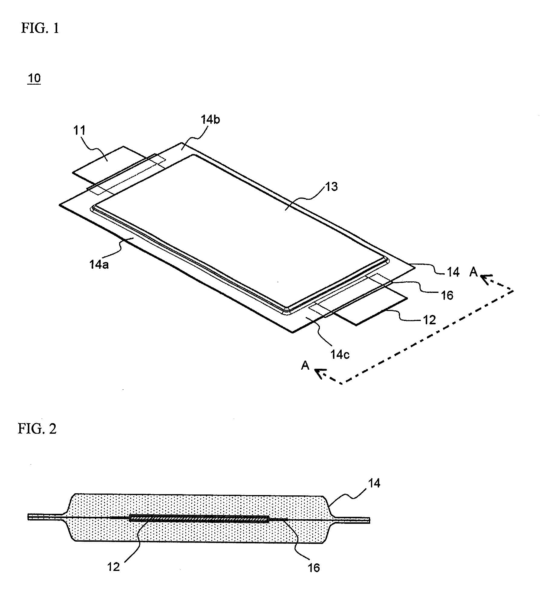
Battery cell of improved safety

a battery cell and safety technology, applied in the field of battery cell safety improvement, can solve the problems of low safety increased safety risks of lithium secondary batteries, fire or explosion, etc., and achieve the effects of reducing the penetration of electrolytes, and reducing the risk of fir

Active Publication Date: 2010-10-21
LG ENERGY SOLUTION LTD
View PDF9 Cites 21 Cited by
  • Summary
  • Abstract
  • Description
  • Claims
  • Application Information

AI Technical Summary

Benefits of technology

[0024]In a preferred embodiment, the metal barrier layer is made of aluminum, exhibiting a gas intercepting property and ductility sufficient to configure in the form of a thin film, or a material containing aluminum. It is required for the outer resin layer to exhibit high resistance against external environment. For this reason, the outer resin layer is preferably made of polymer resin exhibiting more than predetermined tensile strength and weather resistance, such as polyethylene terephthalate (PET) or oriented nylon film. Also, inner resin layer may be made of cast polypropylene (CPP) resin exhibiting a thermally-weldable property (a thermal adhesive property), a low hygroscopic property to restrain the penetration of an electrolyte, and a property not to swell or corrode by the electrode.
[0025]Generally, an electrode assembly used in a pouch-shaped battery cell may be classified as an electrode assembly constructed in a structure in which both a cathode lead and an anode lead are located at one side of an electrode assembly or an electrode assembly constructed in a structure in which a cathode lead and an anode lead are opposite to each other. According to the present invention, the electrode assembly, constructed in a structure in which the cathode lead and the anode lead are opposite to each other, is mounted in the battery case. This opposite-structure battery cell has advantages in that it is easy to electrically interconnect electrode terminals of unit cells of a middle- or large-sized battery module constructed in a structure in which a plurality of battery cells are stacked, and a possibility of short circuits is reduced.

Problems solved by technology

As previously described, a lithium secondary battery has excellent electrical properties; however, the lithium secondary battery has low safety.
For example, when abnormal operations, such as overcharge, overdischarge, exposure to high temperature, and electrical short circuits, of the lithium secondary battery occur, decomposition of active materials and an electrolyte, which are components of the battery, is caused, with the result that heat and gas are generated, and the high-temperature and high-pressure condition caused by the generation of the heat and the gas accelerates the above-mentioned decomposition.
Eventually, fire or explosion may occur.
The safety problem of the lithium secondary battery is even more serious for a middle- or large-sized battery pack having a multi-cell structure.
Since a plurality of battery cells are used in the multi-cell structure battery pack, the abnormal operation of some of the battery cells may cause the abnormal operation of the other battery cells, with the result that fire or explosion may occur, which may lead to a large-scale accident.
However, as the lithium secondary battery is continuously used, i.e., as the lithium secondary battery is continuously charged and discharged, the generating element and the electrically connecting members are gradually degraded.
In the abnormal state of the lithium secondary battery, however, when the BMS does not operate, a possibility of danger increases, and it is difficult to control the battery pack for securing the safety of the battery pack.
As a result, the respective swelling battery cells are further pressurized in the restrictive case, and therefore, a possibility of fire or explosion greatly increases under the abnormal operation condition of the battery pack.
However, the above-mentioned technologies need additional components, such as the open piece or the resin film, with the result that manufacturing costs of the battery increases.
Also, additional processes are required, with the result that the productivity of the battery decreases.
Furthermore, the above-mentioned structures are constructed in a structure in which the predetermined region is opened depending upon the melting point of the predetermined member, with the result that operational reliability is low.
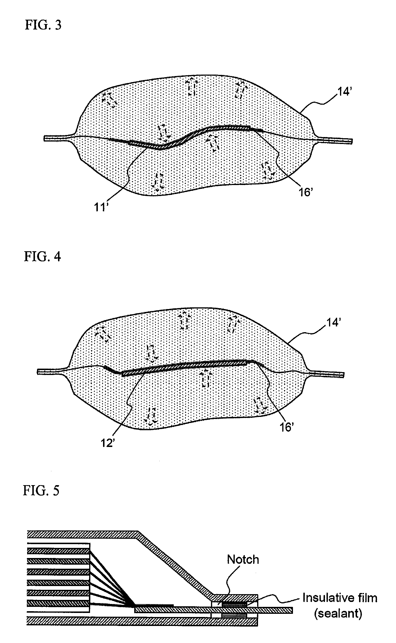
However, when the predetermined notches or non-attachment regions are formed on the insulative film, electrical insulation property of the battery and sealability at the sealing part greatly weaken, with the result that an internal short circuit may occur or external moisture or air is introduced into the battery, whereby the efficiency of the battery lowers.
Furthermore, the stress concentration portions easily respond to even a slight amount of gas generated during the normal operation of the battery, with the result that the sealed state of the battery may be released.

Method used


Image

  • Battery cell of improved safety
  • Battery cell of improved safety
  • Battery cell of improved safety

Examples


example 1

[0064]A mixture including 95 weight percent of LiCoC2, 2.5 weight percent of Super-P (a conducting agent), and 2.5 weight percent of PVdF (a coupling agent), as a cathode active material, was added to NMP (N-methyl-2-pyrrolidone), as a solvent, to manufacture cathode mixture slurry. Also, a mixture including 95 weight percent of artificial graphite, 1 weight percent of Super-P (a conducting agent), and 4 weight percent of PVdF (a coupling agent), as an anode active material, was added to NMP, as a solvent, to manufacture anode mixture slurry. The cathode mixture slurry and the anode mixture slurry were applied to an aluminum foil and a copper foil, respectively, and then the aluminum foil and the copper foil were cut to manufacture cathode plates and anode plates, respectively. The cathode plates and the anode plates were sequentially stacked, while CellGuard™ (TONEN), as separators, was respectively disposed between the cathode plates and the anode plates, to manufacture an electro...

experimental example 1

[0068]Internal pressure increasing experiments were carried out to 30 batteries manufactured according to Example 1 and Comparative examples 1 and 2. The results are indicated in Table 1 below. In the internal pressure increasing experiments, the internal pressure of the respective 30 batteries was increased by 0.1 kgf / mm2 at 30-second intervals using air until wrapping materials of the batteries were vented, and comparison was made between regions where the vent parts were formed.

TABLE 1Number ofNumber ofNumber ofbatteriesbatteriesbatterieshaving ventedhaving ventedhaving vented sideanode leadcathode leadsealing regionssealing regionssealing regionsExample 10300Comparative2730example 1Comparative2919example 2

[0069]As can be seen from Table 1, when the internal pressure increasing experiments were carried out to the 30 batteries manufactured according to Example 1, all of the batteries were uniformly vented at the anode lead sealing regions thereof. Also, the internal pressures of t...


PUM

PropertyMeasurementUnit
internal pressureaaaaaaaaaa
flexibilityaaaaaaaaaa
durabilityaaaaaaaaaa

Abstract

Disclosed herein is a battery cell constructed in a structure in which an electrode assembly is mounted in a battery case made of a laminate sheet including a metal layer and a resin layer, and the battery case is thermally welded along the edge of a receiving part thereof to form a sealing part, wherein a weak part is formed at a portion of the sealing part (‘an electrode lea correspondence portion’) corresponding to one of electrode leads (a, b) connected to the electrode assembly, e.g., the electrode lead (a) having relatively low flexibility, the weak part being physically deformed, such that internal gas is discharged outside through the weak part, when predetermined pressure is applied to the weak part, and the weak part is not formed at an electrode lead correspondence portion of the other electrode lead (b).

Description

FIELD OF THE INVENTION[0001]The present invention relates to a battery cell of improved safety, and, more particularly, to a battery cell constructed in a structure in which an electrode assembly is mounted in a battery case made of a laminate sheet including a metal layer and a resin layer, and the battery case is thermally welded along the edge of a receiving part thereof to form a sealing part, wherein a weak part is formed at a portion of the sealing part (‘an electrode lead correspondence portion’) corresponding to one of electrode leads (a, b) connected to the electrode assembly, e.g., the electrode lead (a) having relatively low flexibility, the weak part being physically deformed, such that internal gas is discharged outside through the weak part, when predetermined pressure is applied to the weak part, and the weak part is not formed at an electrode lead correspondence portion of the other electrode lead (b).BACKGROUND OF THE INVENTION[0002]As mobile devices have been incre...

Claims


Application Information

Patent Timeline
Patent Type & Authority Applications(United States)
IPC IPC(8): H01M2/12H01M50/119H01M50/121H01M50/124H01M50/548H01M50/562
CPCH01M2/0277H01M2/0285H01M2/30H01M2/12H01M2/0287Y02E60/10H01M50/124H01M50/3425Y02P70/50H01M50/562H01M50/121H01M50/548H01M50/119H01M2220/10H01M2220/20H01M50/116H01M50/531
Inventor YOU, SEUNGJAEKIM, MIN SU
Owner LG ENERGY SOLUTION LTD
Why Eureka
Try Eureka