Fuel spray apparatus for gas turbine engine

a gas turbine engine and fuel spray technology, which is applied in mechanical equipment, machines/engines, lighting and heating equipment, etc., can solve the problems of substantial degradation of the cooling effect, insufficient countermeasures to address the problem of coking, and remained fuel in the main fuel passage, so as to effectively blow off leaked fuel, the effect of increasing the flow speed of the purge air in the purge air passage and smooth introduction

Active Publication Date: 2010-10-28
KAWASAKI HEAVY IND LTD
View PDF4 Cites 47 Cited by
  • Summary
  • Abstract
  • Description
  • Claims
  • Application Information

AI Technical Summary

Benefits of technology

[0011]In this invention, it is preferred that the fuel spray apparatus for the gas turbine engine further includes a shroud covering the main fuel passage and the shield body, wherein the shroud is provided with an intake port and a discharge port for the purge air, and wherein the purge air passage is provided between an inner face of an outer circumferential wall of the shroud and the shield body. With this configuration, the purge air passage can be readily provided between the inner face of the outer circumferential wall of the shroud and the shield body.
[0012]Further, it is preferred that a passage area of the intake port for the purge air is greater than a passage area of the discharge port. With this configuration, the flow speed of the purge air in the purge air passage can be adequately increased, thereby effectively blowing off the leaked fuel.
[0013]More preferably, the fuel spray apparatus for the gas turbine engine further includes a guide tube provided downstream of the fuel injection port of the main part, such that the fuel dripping can be blown off from the guide tube by the purge air. With this configuration, the fuel can be smoothly introduced from the fuel injection port, due to the guide tube, upon the high power operation, without being leaked into the surrounding parts or members.
[0014]In this invention, it is preferred that the guide tube is located at an outer circumference of an annular downstream part of the main fuel passage, wherein the shield body has a spring elasticity whereby the guide tube can be pressed with a spring force against the outer circumferential face of the main fuel passage. With this configuration, the guide tube can be adequately pressed with the spring force against the outer circumferential face of the main fuel passage. Therefore, there is no need for separately providing any support member fo

Problems solved by technology

However, such countermeasures cannot sufficiently address the problem of the coking as described above.
For instance, the fuel remained in the main fuel passage may tend to be pushed out by the air entering the fuel passage and leak into surrounding parts or members, such as the shroud constituting the air heat insulating space.
Further, if such leakage of the fuel is continued and the amount of the carbonized fuel (or coking) is rather increased, the fuel passage will be connected with the shroud via the so-carbonized fuel, res

Method used


Image

  • Fuel spray apparatus for gas turbine engine
  • Fuel spray apparatus for gas turbine engine
  • Fuel spray apparatus for gas turbine engine

Examples


Embodiment Construction

[0024]Hereinafter, one preferred embodiment will be described with reference to the drawings.

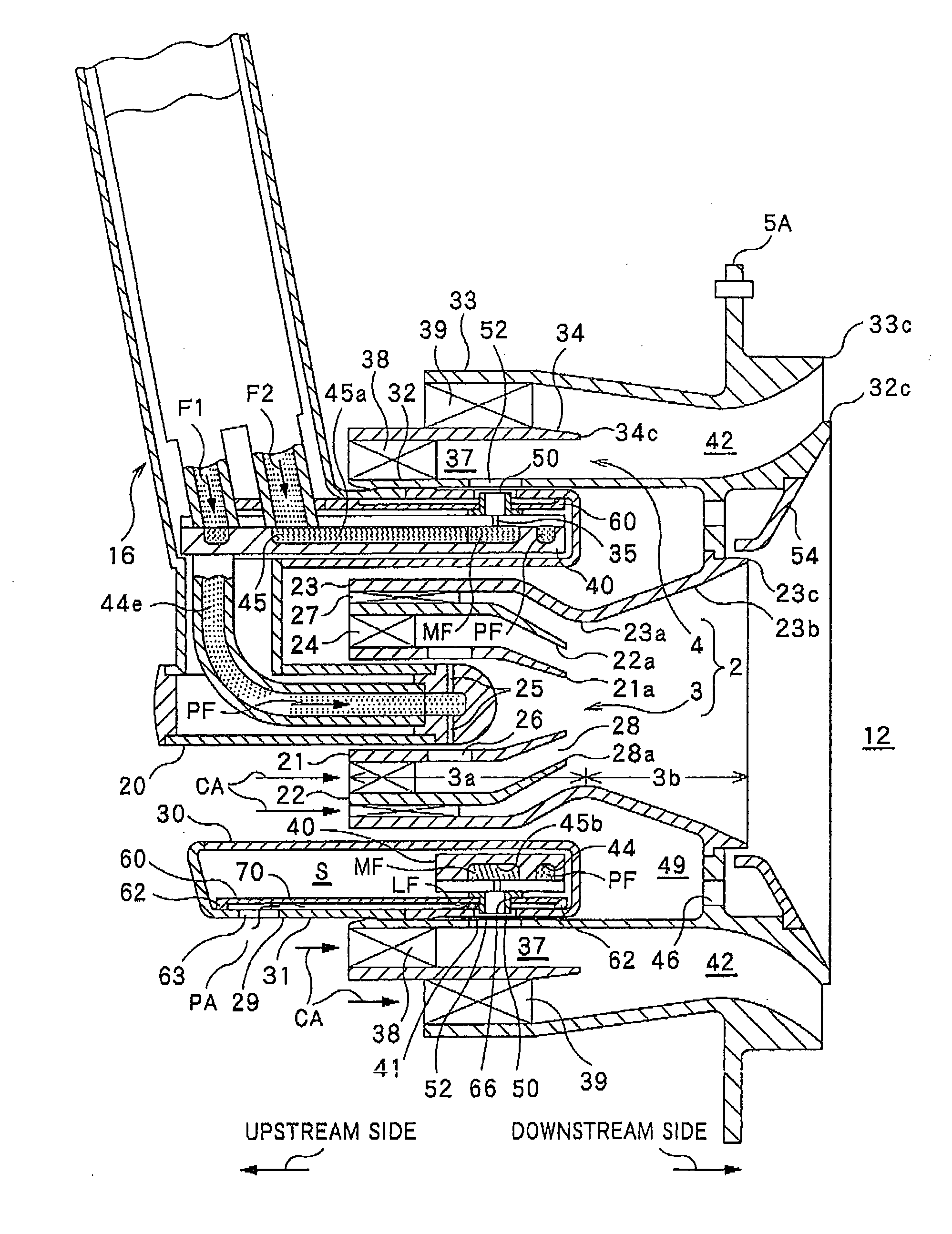
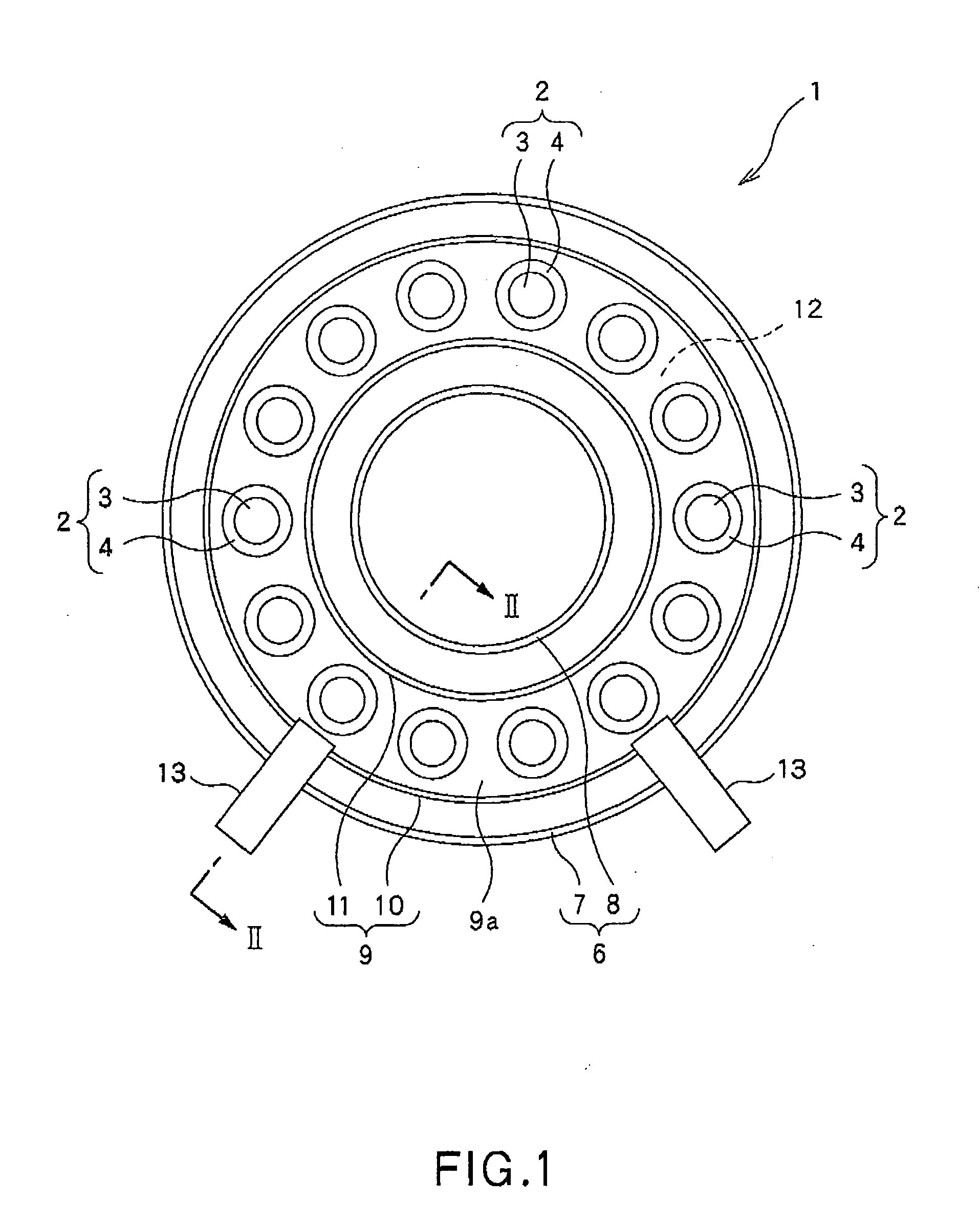
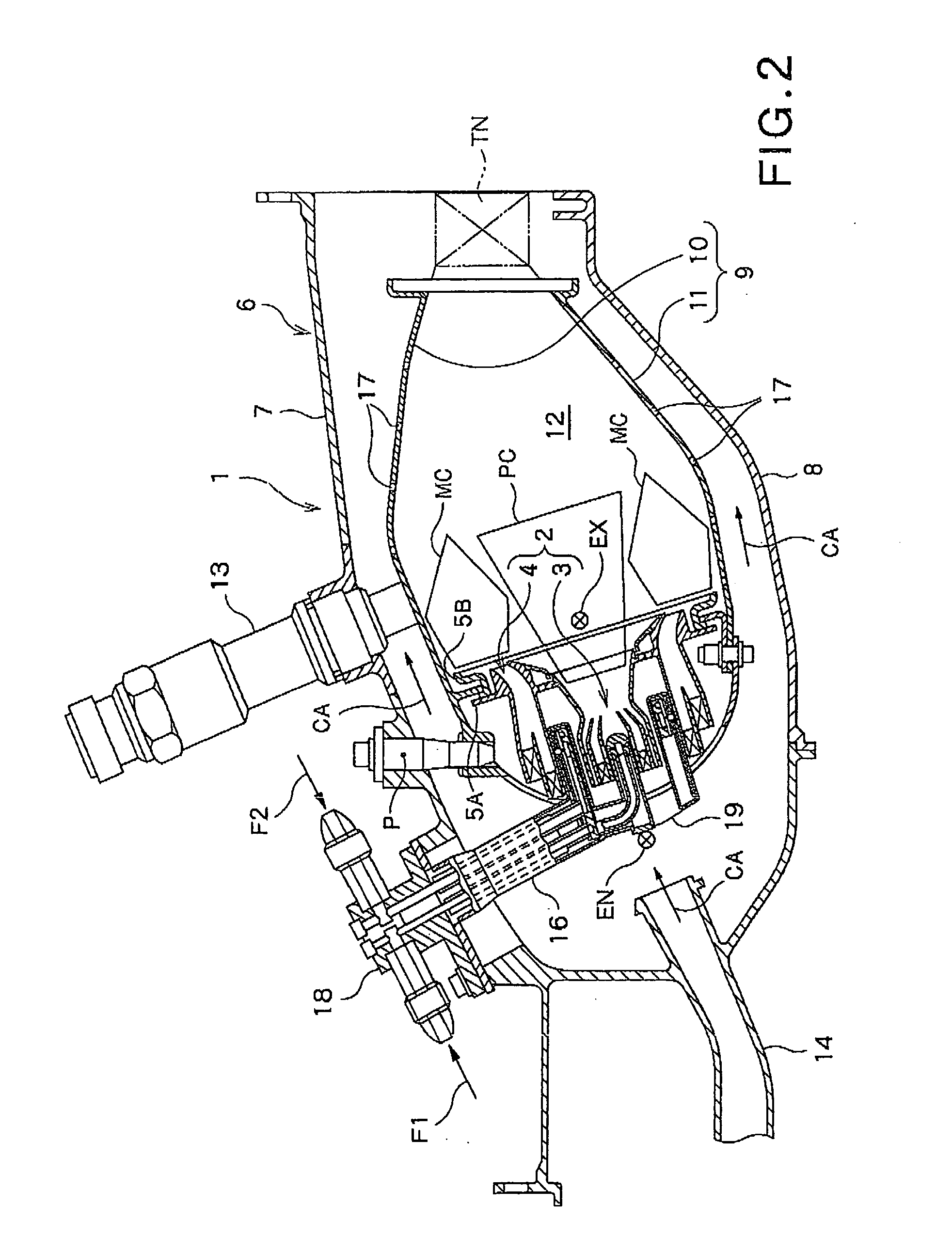
[0025]FIG. 1 shows a head portion of the combustor 1 of the gas turbine engine including the fuel spray apparatus 2 according to the embodiment of the present invention. The combustor 1 can serve to mix the fuel with compressed air supplied from a compressor (not shown) of the gas turbine engine and then combust the fuel with the supplied compressed air in order to drive a turbine by feeding high-temperature and high-pressure combustion gas generated by the combustion into the turbine.

[0026]In this annular type combustor 1, an annular inner casing 8 is concentrically located inside an annular outer casing 7. These annular casings 7, 8 constitute together a combustor housing 6 having an annular internal space provided therein. Further, in this annular internal space of the combustor housing 6, an annular inner liner 11 is concentrically located inside an annular outer liner 10. These annular ...


PUM


Abstract

The present invention provides a fuel spray apparatus for a gas turbine engine, including: a pilot part configured to spray a fuel to be used for a diffusion combustion; a main part provided so as to surround the pilot part and configured to inject a pre-mixed gas only upon a high power operation; and a shield body constituting a purge air passage which is configured to take therein an air flowed on an upstream side relative to a fuel injection port of the main part as a purge air, and to blow off a fuel dripping from the fuel injection port toward a main air passage of the main part. The purge air passage is provided in a position opposite to a main fuel passage communicated with the fuel injection port across the shield body.

Description

CROSS REFERENCE TO RELATED APPLICATIONS[0001]This application is based upon and claims the benefit of priority from the prior Japanese Patent Application No. 2009-107440 filed on Apr. 27, 2009, the entire contents of which are incorporated herein by reference.BACKGROUND OF THE INVENTION[0002]1. Field of the Invention[0003]The present invention relates to a fuel spray apparatus for a gas turbine engine including a staged fuel injector composed of two combustion methods, i.e., a diffusion combustion and a lean-mixture combustion.[0004]2. Background Art[0005]In recent years, reduction of harmful substances, such as nitrogen oxide (NOx) and the like, discharged from a gas turbine has been strictly required for environmental protection. Meanwhile, for the gas turbine, especially for an airplane engine, good altitude relight ability has been required, and thus ability for low-NOx combustion as well as for stabilized combustion has attracted significant attention. Thus, the staged fuel inj...

Claims


Application Information

Patent Timeline
IPC IPC(8): F02C7/22
CPCF23D11/386F23D2209/30F23D2214/00F23D2900/00008Y02T50/675F23R3/10F23R3/283F23R3/343F23R3/50F23D2900/00018Y02T50/60
Inventor NONAKA, YOSHIHARUKOBAYASHI, MASAYOSHIOGATA, HIDEKI
Owner KAWASAKI HEAVY IND LTD
Why Eureka
Try Eureka