Cryopreservation device

Active Publication Date: 2010-11-04
TAIYO NIPPON SANSO CORP
View PDF8 Cites 31 Cited by
  • Summary
  • Abstract
  • Description
  • Claims
  • Application Information

AI Technical Summary

Benefits of technology

[0032]According to the present invention, since the putting-in/out work space section is filled with a dry gas, the inside of the putting-in/out work space section can be kept in a dry state. Further, it is possible to restrain frost from adhering to those and the cryopreservation vessel at the time of putting an ampoule and an ampoule storing tool into and out of a cryopreservation vessel. Therefore, it is possible to easily perform reading of sample management codes addressed on the surface of an ampoule, and reduce the frequency of maintenances for the cryopreservation vessel.
[0033]Moreover, since the putting-in/out work space section is filled with a dry gas to be at positive pressure, the atmosphere is prevented from invading, and the atmosphere containing dust, bacteria, viruses, and the like, and exhaled air of a worker are restrained from mixing into the putting-in/out work space section. Further, the putting-in/out work space section can be kept in a dry state and a clean state, which makes it possible to prevent contamination of ampoules.
[0034]Further, since the humidity in the putting-in/out work space section is monitored by a dew point meter, and a dry gas is introduced into the putting-in/out work space section in the case where a dew point rises, the inside of the putting-in/out work space section is always kept in a dry state, which makes it possible to certainly prevent front formation.
[003

Problems solved by technology

Further, when the ampoule is stored in the ampoule storing tool or when the ampoule storing tool is stored in the cryopreservation vessel, the storing work is difficult due to frost adhering to be deposited on the ampoule storing tool in some cases.
When frost adheres to an ampoule, it is difficult to read the management code addressed on the surface of the ampoule, that causes a malfunction of

Method used


Image

  • Cryopreservation device
  • Cryopreservation device
  • Cryopreservation device

Examples


Embodiment Construction

[0075]Hereinafter, an embodiment of the present invention will be described with reference to FIGS. 1 to 7.

(Glove Box)

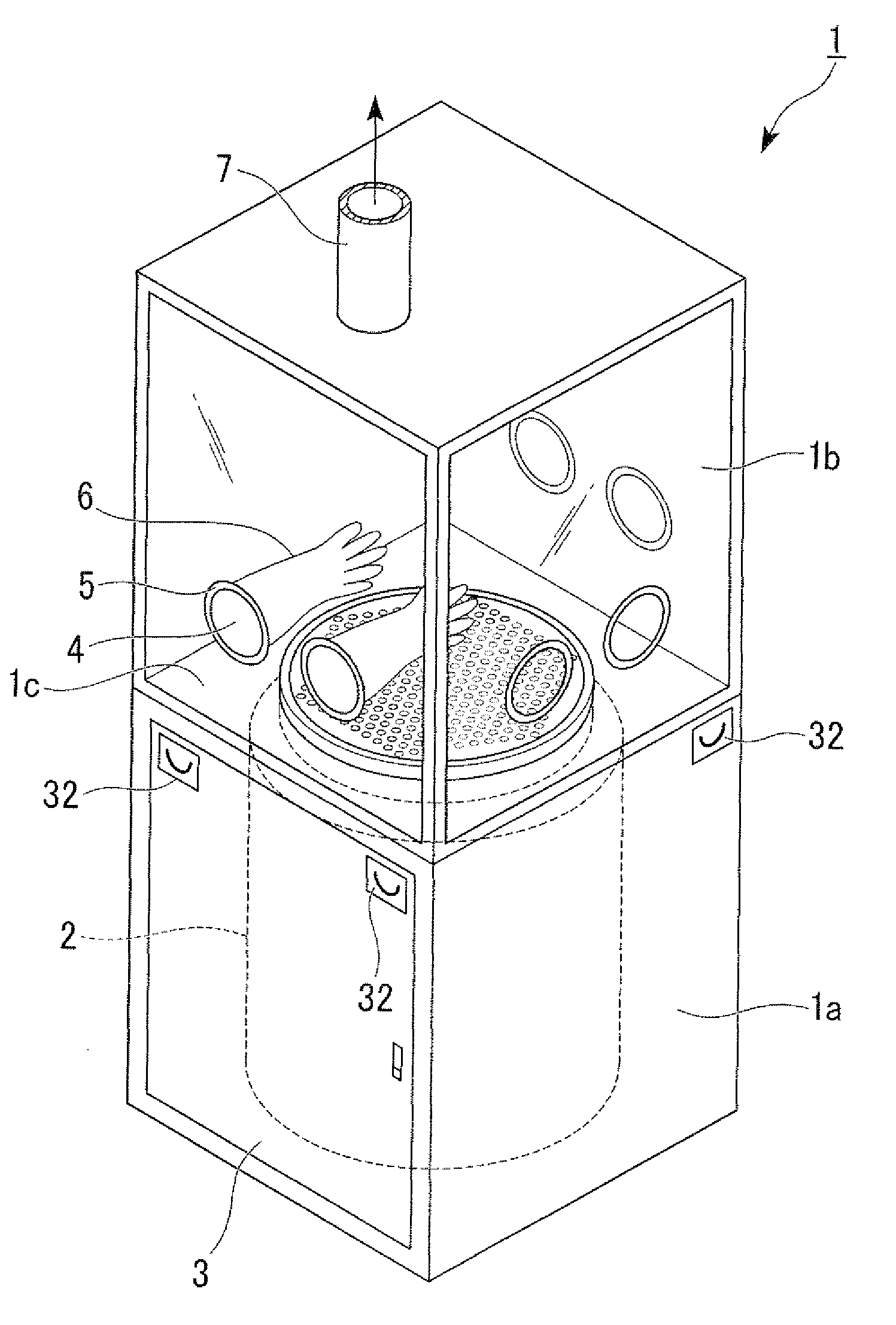
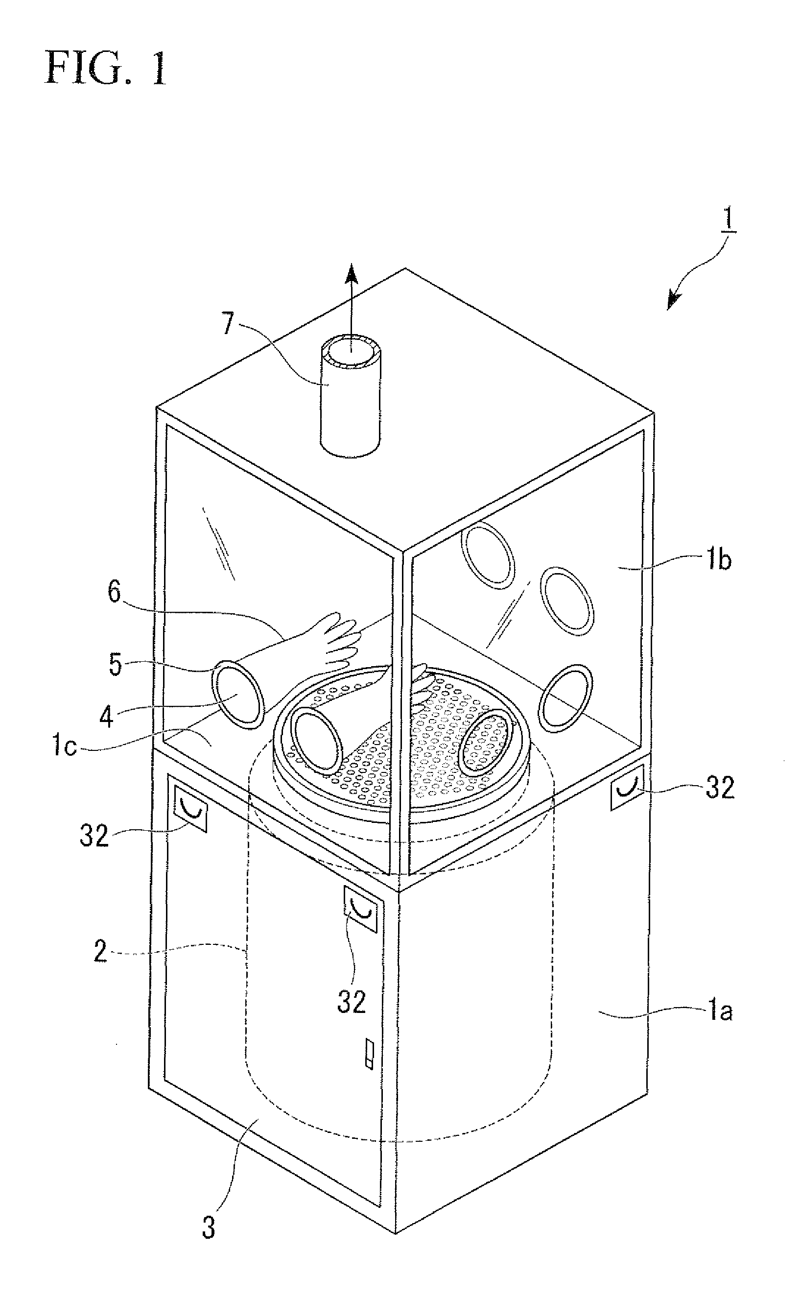
[0076]FIG. 1 is a schematic block diagram showing an example of a glove box 1 of the present invention. The glove box 1, in this example is a rectangular parallelepiped box whose outside dimension is approximately 2,000 mm high, 1,000 mm wide, and 1,000 mm deep.

[0077]This glove box 1 is in a vertical direction divided into two with a partition board 1c, that is comprised of a putting-in / out work space section (hereinafter referred as to a work space section) 1b in the upper portion and a housing section 1a in the lower portion. The sizes and shapes of the housing section 1a and the work space section 1b are respectively cubes of approximately 1,000 mm on a side.

[0078]A cryopreservation vessel 2 can be housed in the housing section 1a, and a circular through hole is formed in the center of the partition board 1c, and the glove box 1 is configured to be capable of appr...


PUM


Abstract

A cryopreservation vessel of the present invention includes a vessel body which holds a low-temperature liquefied gas, a cap which closes an opening section of the vessel body and has a plurality of through holes that are formed so as to pass through in a vertical direction, and ampoule storing tools which are housed so as to be able to pass through the through holes of the cap, and the ampoule storing tools are each comprised of a support pillar and a plurality of ampoule storing sections which are equipped with the support pillar so as to be arrayed in a vertical direction of the support pillar.

Description

TECHNICAL FIELD[0001]The present invention relates to a glove box (i.e. a cryopreservation device) that houses a cryopreservation vessel, and particularly to a glove box that is configured to be capable of preventing frost formation onto the ampoules or the like when ampoules housed in the cryopreservation vessel are taken in and out.[0002]Priorities are claimed on Japanese Patent Application No. 2008-009393 filed on Jan. 18, 2008 and Japanese Patent Application No. 2008-268768 filed on Oct. 17, 2008 in Japan, the contents of which are incorporated herein by reference.BACKGROUND ART[0003]As a method for simply storing biological samples such as spermatozoa, embryo, and cells of experimental animals used for development of new medicines or medical basic research, a cryopreservation method is generally used. In particular, a cryopreservation method using liquefied nitrogen is considered to be capable of most stably storing biological samples for a long period, and is broadly used.[000...

Claims


Application Information

Patent Timeline
IPC IPC(8): F17C13/00B25J21/02A47B81/04G01N25/02
CPCA01N1/0263A01N1/0257
Inventor YOSHIMURA, SHIGEHIROTAKEUCHI, MASAHIROFUJITA, MAMORUOHTA, HIDETOSHI
Owner TAIYO NIPPON SANSO CORP
Why Eureka
Try Eureka