Biomass center air jet burner

a technology of biomass and air jets, which is applied in the direction of lighting and heating apparatuses, combustion types, and combustion using lumps and pulverizing fuels, etc., can solve the problems of reducing the heat output of biomass fuels, requiring considerably more fuel mass to achieve the effect of a comparable heat output, and affecting the combustion efficiency of biomass fuels

Inactive Publication Date: 2010-11-04
BABCOCK & WILCOX POWER GENERATION GRP INC
View PDF30 Cites 17 Cited by
  • Summary
  • Abstract
  • Description
  • Claims
  • Application Information

AI Technical Summary

Benefits of technology

[0015]Embodiments of the present invention provide a superior method and apparatus for co-firing biomass in combination with pulverized coal.
[0017]In embodiments of the present invention, the apparatus includes a forced draft fan providing a first supply of air to the windbox, a core air duct, enclosing the core air zone, for receiving a core portion of the first supply of air, the core air duct having a core damper for regulating the core portion entering the core air duct, a core nozzle for receiving the core portion from said core air duct, the core nozzle delivering said core portion to said burner throat, a burner elbow for receiving pulverized coal and a second supply of air, the pulverized coal and said second supply of air continuing through a coal nozzle in an annulus formed between the core nozzle and the coal nozzle, the core portion serving to accelerate ignition of pulverized coal by contacting an inner cylinder of a coal jet leaving the coal nozzle, the core portion also serving to accelerate combustion.

Problems solved by technology

Firing biomass fuels faces many technical challenges.
Nevertheless, firing biomass in place of coal requires considerably more fuel mass to achieve a comparable heat output.
Further, while the highly-volatile nature of biomass makes the fuel inherently easy to burn, the high moisture content can delay ignition.
Delayed ignition is especially undesirable in suspension firing,
This technique is however limited in practicality due to the resulting burner nozzle velocity necessary to maintain both types of particles in suspension.
Excessive burner nozzle velocity results in flame instability, delayed ignition, and poor combustion performance.

Method used


Image

  • Biomass center air jet burner
  • Biomass center air jet burner
  • Biomass center air jet burner

Examples


Embodiment Construction

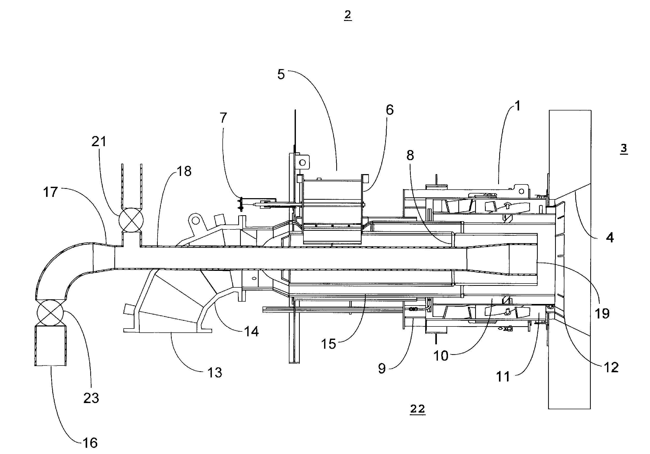
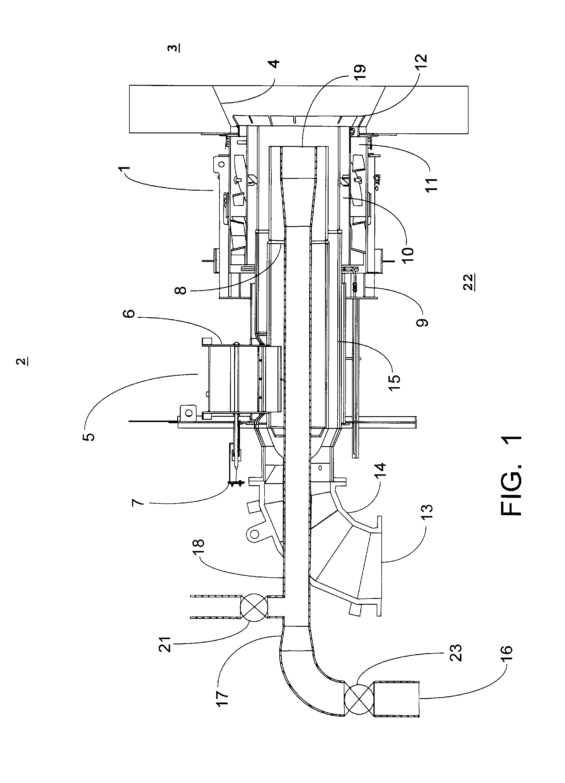
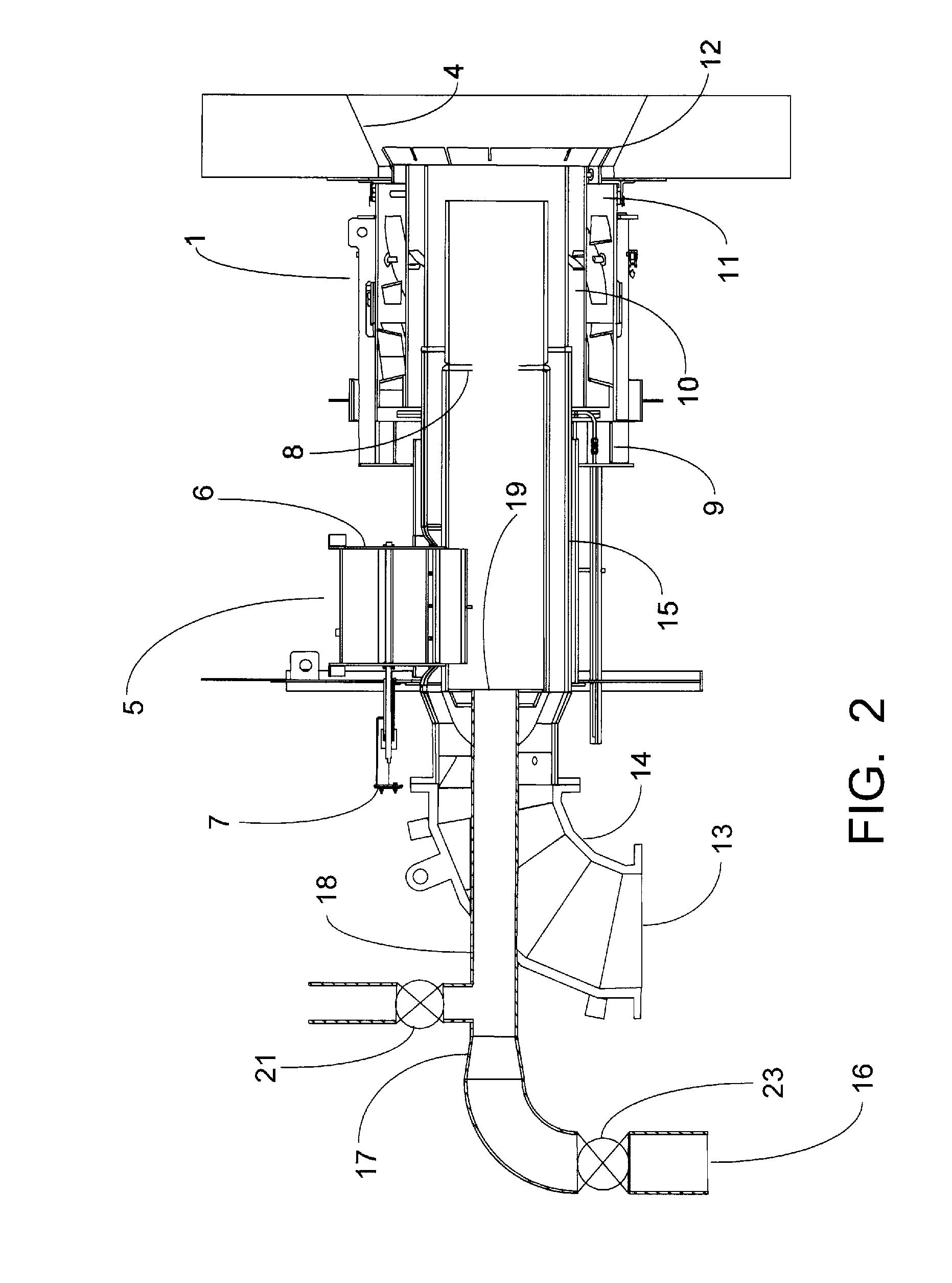
[0024]Referring now to figures, wherein like references designate the same or functionally similar elements throughout the several drawings, FIG. 1 shows a burner assembly 1 residing within windbox 2, which is attached to the furnace 3 of a boiler (not shown). Secondary air 22 is provided to windbox 2 by a forced draft fan (not shown) and heated by an air preheater (not shown). The burner assembly 1 is connected to furnace 3 by burner throat 4, through which air and fuel supplied to the burner assembly 1 are emitted into the furnace 3. A portion of the secondary air 22 constitutes core air 5. Core air 5 enters core air duct 6 and is regulated by core air damper 7. Core air 5 continues through the burner assembly 1 through core nozzle 8, exiting through the burner throat 4.

[0025]Secondary air 22 is also supplied to the burner assembly (designated as secondary air to the burner assembly 9). Secondary air 22 enters the burner assembly 1 and travels through parallel flow paths of the in...


PUM


Abstract

A combustion apparatus capable of firing biomass fuel including a burner assembly which includes a biomass nozzle concentrically surrounded by a core air zone and extending axially along the length of the core air zone, the burner assembly residing within a windbox, the windbox being attached to a furnace of a boiler, and the burner assembly being connected to the furnace by a burner throat, through which air and fuel supplied to the burner assembly are emitted into the furnace.

Description

FIELD OF THE INVENTION[0001]The present invention relates generally to the field of industrial burner apparatuses for performing combustion functions for power generation.[0002]As used herein the term “biomass” describes a wide range of organic matter derived from diverse living, or recently-living organisms, such as grasses and wood products. Sources of biomass include trees, shrubs, bushes, residual vegetation from harvesting grains and vegetables. Biomass is commonly plant matter harvested to generate electricity or produce heat. Biomass may also include biodegradable wastes of organic origin that can be burned as fuel.[0003]Biomass differs from fossil fuels, which are hydrocarbons found within the top layer of the Earth's crust. Common examples of fossil fuels include coal and oil. Unlike fossil fuels, biomass fuels are generally considered CO2 neutral and renewable resources, since CO2 generated from biomass combustion can be removed from the atmosphere by the plants that provi...

Claims


Application Information

Patent Timeline
Patent Type & Authority Applications(United States)
IPC IPC(8): F23G5/08F23L5/02F23D1/00F23C5/08
CPCF23C7/004F23C2201/20F23C2900/06043F23G2209/26F23D2201/00F23G7/10F23D1/00
Inventor LARUE, ALBERT DMONACELLI, JOHN E.
Owner BABCOCK & WILCOX POWER GENERATION GRP INC
Why Eureka
Try Eureka