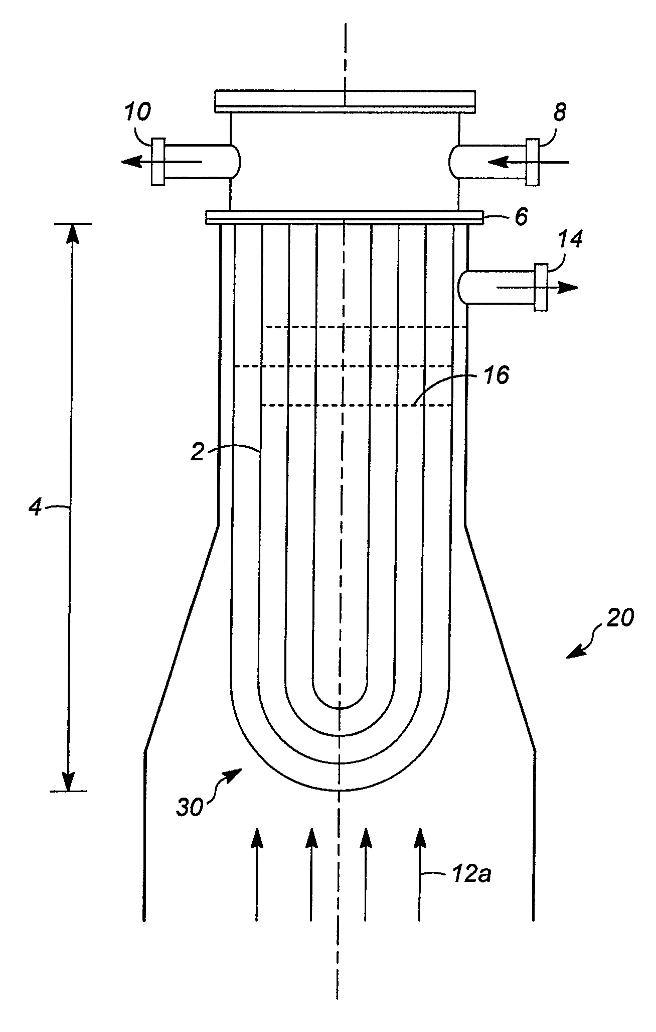
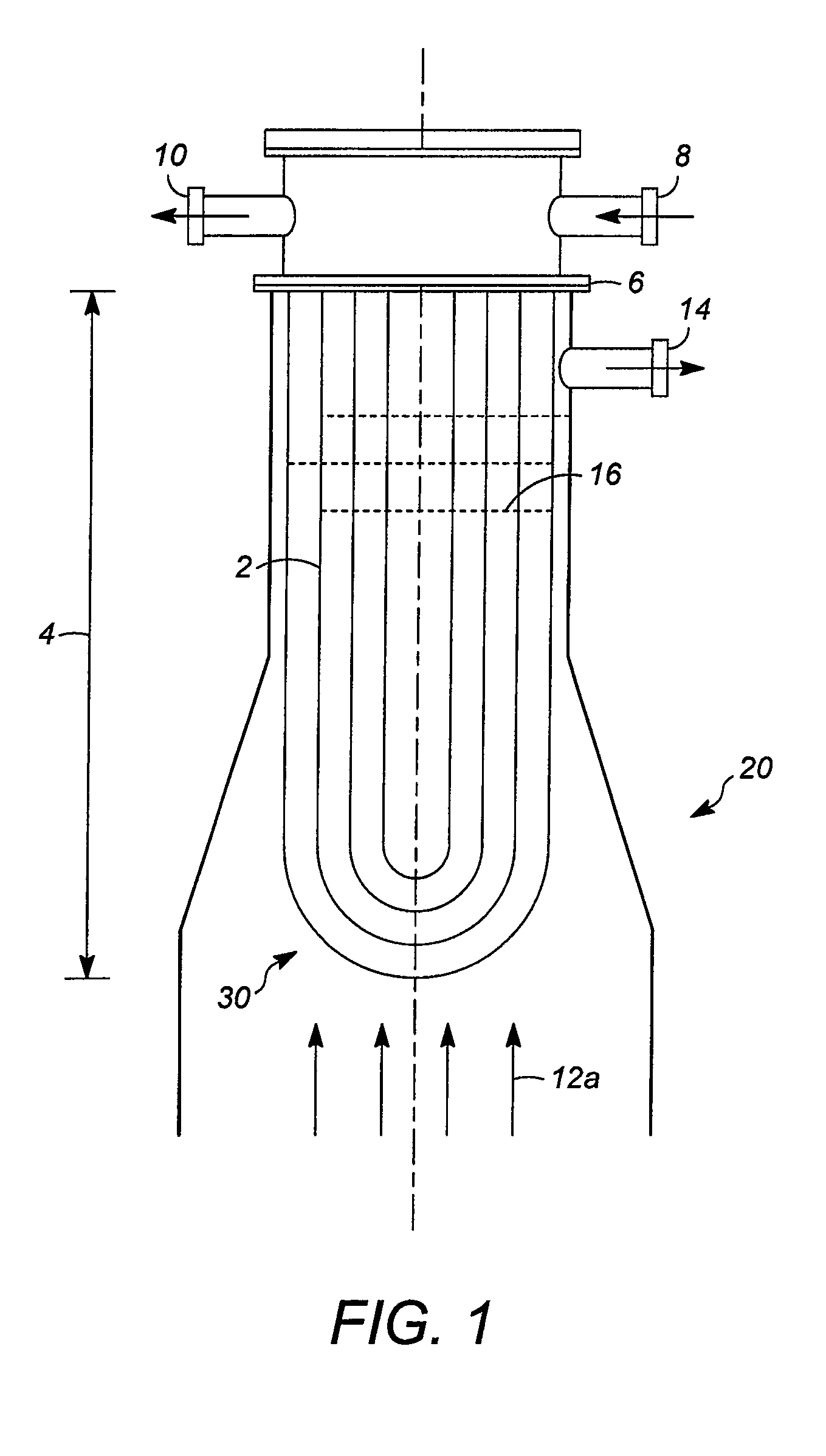
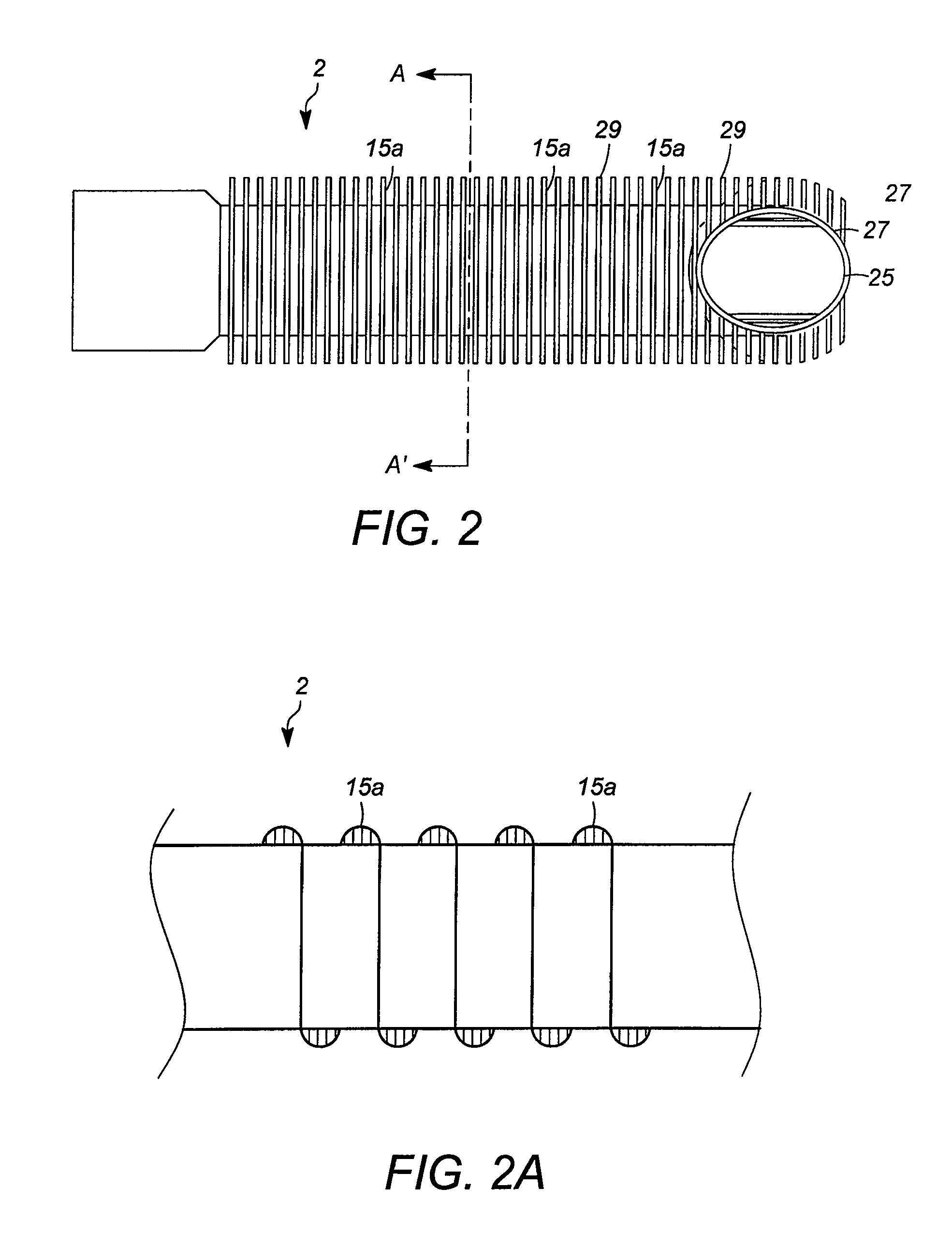
[0010]The present invention is associated with the discovery of improvements in heat exchangers comprising tube bundles and particularly internal tubular condensers disposed within vapor-liquid contacting apparatuses such as
distillation columns. Aspects of the invention relate to condenser tubes having surface enhancements that improve their performnance, especially when aligned or extending substantially vertically within a section (e.g., an overhead section) of the length of a vertically oriented column. The surface enhancements of the tubes beneficially improve their
heat transfer coefficient and consequently the overall heat exchange capacity of an internal tubular condenser bundle of a given size that employs these tubes. This higher capacity in some instances (e.g., in the case of large columns and / or columns operating in low pressure drop /
low mass velocity regimes) can overcome the requirement to use more costly heat exchangers such as welded plate or external heat exchangers. In particular, the tube surface enhancements described herein can increase the
heat transfer coefficient of tubes used in a tubular condenser such that the required exchanger area is reduced to below that which corresponds to a practical size limit (e.g., about 1.5 meters (5 feet)
diameter of the tube bundle) or weight limit for installation at the top of a distillation column.
[0014]Representative surface enhancements include shaped recessions, circumferentially extending fins, axially extending fins, or a combination of these. In the case of circumferentially extending fins, the fins may be characteristic of those used for “low finned” tubes, with the fins having a height from about 0.76 mm (0.03 inches) to about 3.8 mm (0.15 inches). Circumferentially extending fins generally refer to a plurality of “plates” that are spaced apart (e.g., uniformly or at regular intervals) along the axial direction of the tube. The plates of circumferentially extending fins, in an alternative embodiment, may be provided by a single, continuously wound,
helical spiral rather than discreet extensions. In either case, the plates often each have an outer edge (or outer perimeter), with a
single tube extending through central sections of a plurality of plates. The outer edges of the plates may be circular or may have some other geometry, such as rectangular or elliptical. In the case of circumferentially extending fins, further tube surface enhancements can include one or more notches on the outer edges of all or a portion of these fins or plates, where the notches may be spaced apart radially about the edges, for example, in a uniform manner or at a constant radial spacing. In other embodiments, non-uniform radial spacing may be used. In the case of tubes used in a vertically aligned tube bundle of a condenser, it may be desirable to align the notches axially with respect to adjacent fins (i.e., the immediately higher and / or lower circumferentially extending fins). The axial alignment of these notches, such that they may be superimposed when viewed axially, can improve condensate drainage.
[0016]Alone or in combination with surface enhancements, the tubes themselves, while extending in a generally linear direction, may have, in at least one region of the tubes used for heat transfer as described above, a non-linear central axis, which can provide a non-linear internal flow path for fluid flow through the tubes. For example, the tubes, as well as their internal central axes, may have a wave, jagged, or
helical (coiled) shape to
increase pressure drop and / or fluid mixing. Otherwise, an overall
helical fluid flow path can be provided, for example, in the case of a flattened or eccentric profile tube (e.g., having a rectangular cross-section or otherwise an oval-shaped or elliptical cross section) that has a twisted tube geometry (i.e., such that a major axis of the cross-sectional shape, for example the major axis of an
ellipse, rotates
clockwise or counterclockwise along the linear direction of the tube). In the case of a twisted tube geometry, the central axis of fluid flow may be linear or non-linear (e.g., helical). Adjacent tubes extending generally linearly, for example in a distillation column section where heat transfer takes place, but having a wave, jagged, or helical shape or a twisted tube geometry may have a plurality of external contact points with adjacent tubes, with these contact points possibly being evenly spaced apart by regions where the adjacent tubes are not in contact. Such spaced apart contact points with one or more adjacent tubes can physically stabilize the positions of the tubes and even avoid the need for baffles or tube supports.
[0018]In addition to their exterior surfaces, the tube internal surfaces may be modified to improve heat transfer capability. For example, all, a majority, or at least a portion of the tubes in the tube bundle may have internal surfaces, at least in a region of the tubes that extends (e.g., vertically or horizontally) over a section of the column length, onto which a
coating is bonded. If a
coating is used, it is generally bonded to at least a region of the tubes (e.g., where condensation occurs on the external tube surfaces) having the surface enhancement(s), as discussed above, on outer or external surfaces. A representative internal tube
surface coating comprises a porous metallic matrix that can improve the
internal heat transfer coefficient of the tube and consequently the overall heat exchange capacity of a condenser using the tubes. Some suitable coatings are referred to as enhanced boiling
layers (EBLs), which are known in the art for their applicability to heat transfer surfaces on which boiling occurs, and particularly for their ability to achieve a high degree of heat transfer at relatively low temperature differences. An EBL often has a structure comprising a multitude of pores that provide boiling
nucleation sites to facilitate boiling.
[0020]In addition to EBLs, another internal enhancement for condenser tubes involves the use of one or a plurality of ridges, which may, for example, be in the form of a spiral or multiple spirals. Such ridges may be used to further improve the transfer of heat, and particularly
sensible heat, across the internal tube surface. Internal ridges may be used alone or in combination with other features of condenser tubes as described herein. Further internal enhancements include twisted tape, wire matrix inserts (e.g., from Cal-Gavin Limited, Warwickshire, UK), and other in-tube heat transfer devices that can enhance the tubeside
heat transfer coefficient.


