
Bolometric detector for detecting electromagnetic radiation in the region extending from infrared to terahertz frequencies and an array detection device comprising such detectors

a detector and electromagnetic radiation technology, applied in radiation pyrometry, instruments, material analysis, etc., can solve the problems of resistive load shape, inability to pick up inability to detect all available electromagnetic power, etc., to limit the absorption of stray radiation

Active Publication Date: 2010-11-04
COMMISSARIAT A LENERGIE ATOMIQUE ET AUX ENERGIES ALTERNATIVES
View PDF5 Cites 30 Cited by
  • Summary
  • Abstract
  • Description
  • Claims
  • Application Information

AI Technical Summary

Benefits of technology

The present invention proposes a resistive bolometric detector with two crossed bow-tie antennas that are not coupled to each other. The detector has a resistive load that converts the collected electromagnetic power into calorific power. A bolometric micro bridge structure suspended above the substrate by support and thermal isolation arms with the resistive load and a bolometric or thermometric element coupled to the resistive load is used to detect the calorific power. The detector has reduced coupling between the antennas, especially coupling via a material, which allows for optimal impedance matching and decoupling of the conversion function from the impedance matching function. The invention also provides an array detector for detecting electromagnetic radiation in the region extending from infrared to terahertz frequencies.

Problems solved by technology

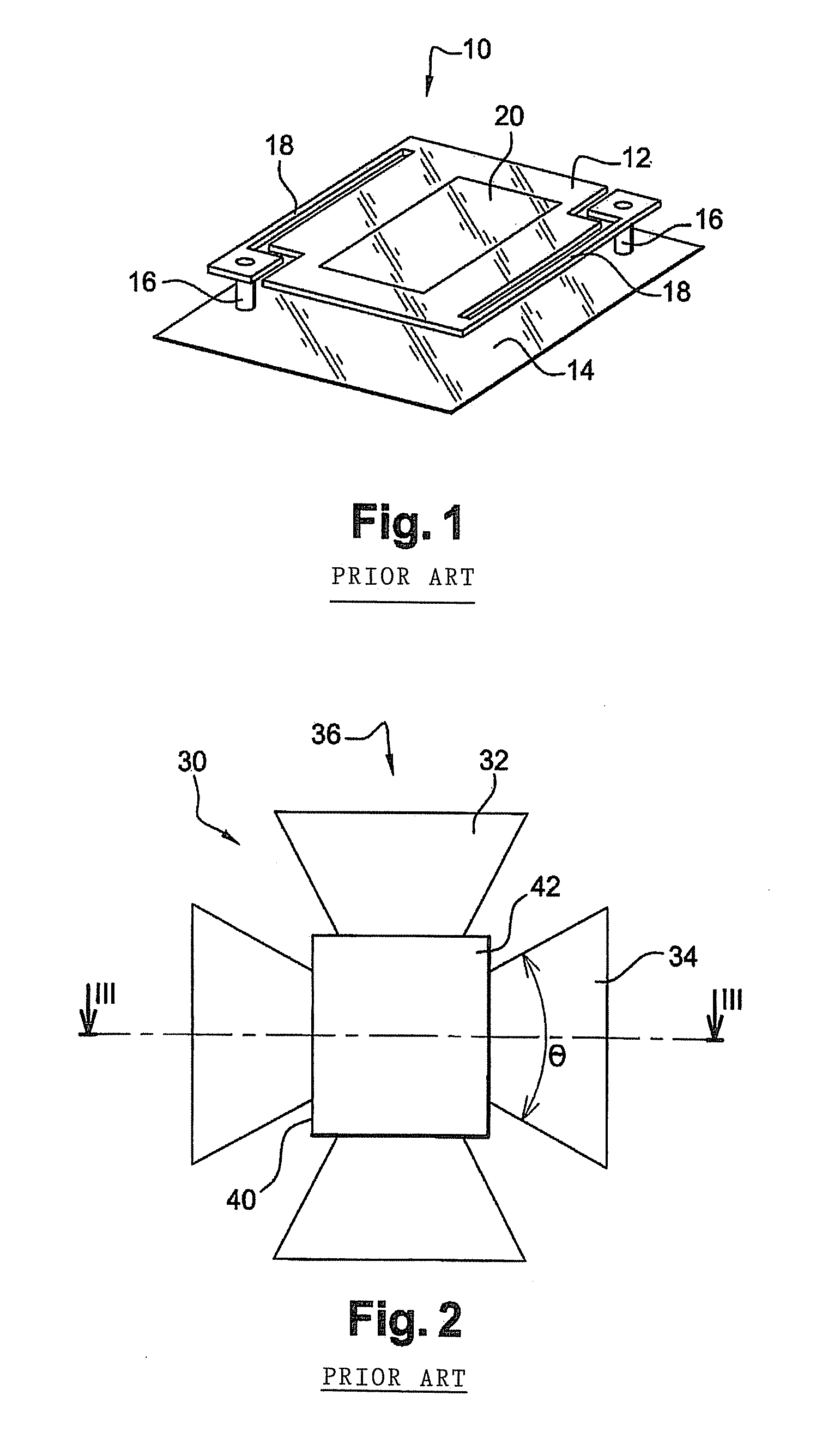
However, with such dimensions, the calorific mass, mechanical strength and radiation losses of the membrane are so problematic that they ultimately have an adverse effect on the efficiency of the detector.
In addition, in most cases, the incident electromagnetic radiation is not polarized so receiving it using just one antenna therefore makes it impossible to pick up all the available electromagnetic power.
However, the shape of the resistive load poses problems in terms of impedance matching.
However, reducing the distance between the antennas and the load to a value of 100 to 200 nm poses difficulties in terms of physical phenomena (Casimir effect affecting mechanical stability, significant radiative heat transfer resulting in deterioration in thermal isolation of the thermoelectric element and hence a drop in the sensitivity of the detector) as well as current fabrication techniques (control of residual stresses in layers to prevent unwanted contacts or control of sacrificial layers used to form the gap between the antennas and the resistive load).
Not only that, increasing the size of the resistive load in order to increase the opposite-facing surfaces presents exactly the same problems as those that led one to separate the receive function and the conversion and thermometric functions as stated earlier.
Due to inherent design features, this results in unwanted, practically optimal coupling with the infrared radiation emitted by bodies at 300° K. which is very difficult to eliminate effectively without impairing the quality of the signal in the terahertz frequency range.
Because of this, it is difficult to obtain optimum impedance matching and capacitive coupling using a resistive load associated with two antennas and having a square shape in the centre of the detector without, at the same time, also making coupling of the detector with infrared radiation optimal.
It is observed that the gain of the detector is substantially reduced, thus making its use relatively unsatisfactory.
Thus, it is not possible to reduce decoupling between the antennas by choosing the substrate accordingly without also significantly modifying the layout and operation of the electronic elements integrated in the substrate.

Method used


Image

  • Bolometric detector for detecting electromagnetic radiation in the region extending from infrared to terahertz frequencies and an array detection device comprising such detectors
  • Bolometric detector for detecting electromagnetic radiation in the region extending from infrared to terahertz frequencies and an array detection device comprising such detectors
  • Bolometric detector for detecting electromagnetic radiation in the region extending from infrared to terahertz frequencies and an array detection device comprising such detectors

Examples


Embodiment Construction

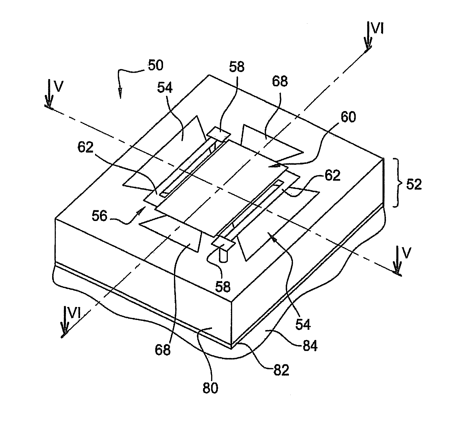
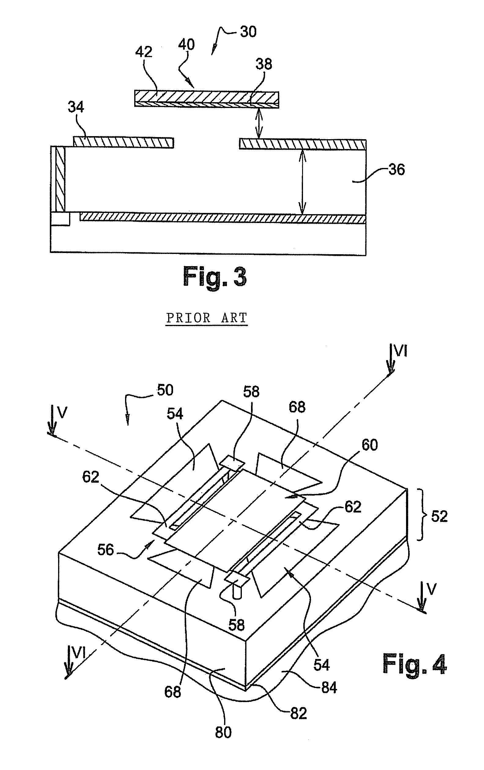
[0060]An elementary bolometric detector 50 according to a first embodiment of the invention which is part of an array of elementary detectors is described below, making reference to FIGS. 4 to 7.

[0061]Bolometer 50 comprises insulating substrate 52 on which a first planar bow-tie antenna 54 made of a conductive material is deposited as well as a micro bridge 56 which is suspended above substrate 52 by two conductive posts 58.

[0062]Micro bridge 56 is formed by central part 60 and two thermal isolation arms 62 which connect central part 60 to posts 58 at right angles to the main axis (V-V) of first antenna 54. Micro bridge 56 comprises a first electrically insulating layer 64, a conductive layer 66 and, more especially, a metal film deposited on insulating layer 64.

[0063]A second bow-tie antenna 68 made of a conductive material and located crosswise relative to first antenna 54 and having its main axis (VI-VI) parallel to thermal isolation arms 62 is also formed on conductive layer 66 ...


PUM


Abstract

This bolometric detector for electromagnetic radiation comprises: a first and a second crossed bow-tie antenna intended to collect electromagnetic radiation; a resistive load coupled to said antennas in order to convert the collected electromagnetic power into calorific power; a bolometric micro bridge structure suspended above substrate by support and thermal isolation arms with the micro bridge comprising: the resistive load; a thermometric element coupled to resistive load so that its temperature can rise due to the effect of the calorific power produced. The first antenna is located outside micro bridge and is capacitively coupled with the resistive load and the second antenna is located in micro bridge and is resistively coupled with the resistive load.

Description

DOMAIN OF THE INVENTION[0001]The present invention relates to the field of antenna-based bolometric detectors and, more especially, detectors with two crossed bow-tie antennas designed to detect electromagnetic radiation in the region extending from infrared and, in particular the 3-5 μm and 8-14 μm bands, to terahertz frequencies.[0002]Detection in the infrared range has many applications which are already widely known. As for terahertz frequencies, i.e. the range of frequencies from 100 GHz to 10 terahertz, envisaged applications include the following (this list is not exhaustive):[0003]medical diagnostics where terahertz detection gives access to details of anatomical structure and chemical reactions which take place therein; neither x-rays or ultrasound provide this information;[0004]military and flight safety applications, e.g. the construction of anti-stealth radar systems or high-resolution radars which provide good target discrimination;[0005]studying and detecting atmospher...

Claims


Application Information

Patent Timeline
Patent Type & Authority Applications(United States)
IPC IPC(8): G01J5/24H01Q9/16
CPCG01J5/08G01J5/20G01J5/10G01J5/0837
Inventor OUVRIER-BUFFET, JEAN-LOUIS
Owner COMMISSARIAT A LENERGIE ATOMIQUE ET AUX ENERGIES ALTERNATIVES
Learn More