Polyimide tube, process for producing the same and fixing belt

Active Publication Date: 2010-11-04
SUMITOMO ELECTRIC IND LTD +1
View PDF7 Cites 21 Cited by
  • Summary
  • Abstract
  • Description
  • Claims
  • Application Information

AI Technical Summary

Benefits of technology

[0058]A polyimide tube according to the present invention has high thermal conductivity, is excellent in terms of mechanical strength and compressive strength, and provides a high fixing property and an excellent offsetting property. Such a polyimide tube excellent in terms of various characteristics can be produced by a process for producing a polyimide tube according to the present invention. A fixing belt according to the present invention including such a polyimide tube excellent in terms of various chara

Problems solved by technology

However, SUS tubes are expensive in terms of material cost and processing cost and hence have a problem of the costs.
SUS tubes also have a problem in that SUS tubes have poor flexibility and hence end portions and the like of the SUS tubes tend to suffer from cracking, for example, when paper sheets are caught in the SUS tubes.

Method used


Image

  • Polyimide tube, process for producing the same and fixing belt
  • Polyimide tube, process for producing the same and fixing belt
  • Polyimide tube, process for producing the same and fixing belt

Examples


example 1

[0111]Carbon nanotubes and boron nitride (“MBN-010T” manufactured by Mitsui Chemicals, Inc.; graphite-structure BN; specific gravity: 2.27) were added to U varnish S (polyimide precursor varnish) respectively in 15 volume percent and 15 volume percent relative to the total volume of the solid content (the volume of the solid content in the varnish is defined as 100 volume percent). The resultant mixture was pre-stirred with a stirrer, mixed with a triple roll mill, and subsequently subjected to vacuum degassing. Thus, a polyimide varnish containing the above-described components was prepared.

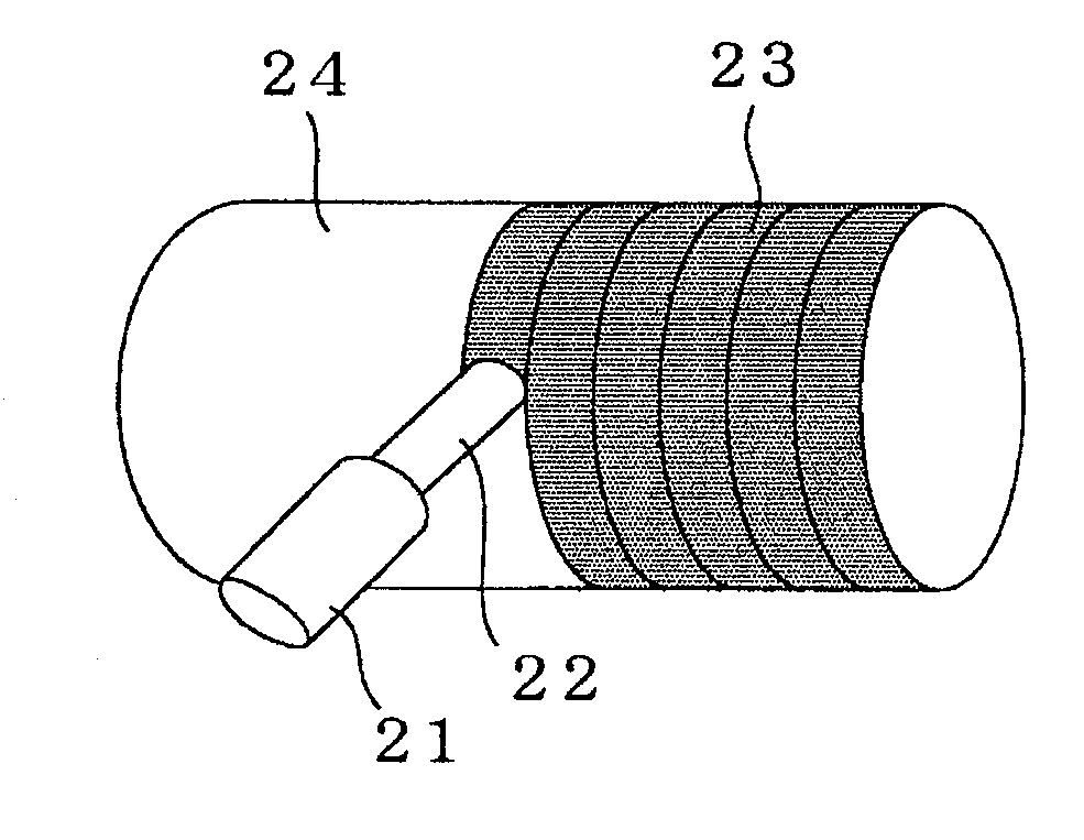
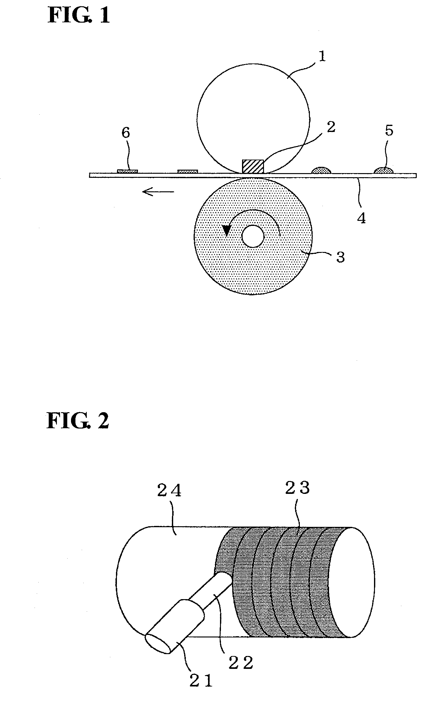
[0112]A core member used was an aluminum cylinder having an outer diameter of 20 mm the outer surface of which was coated with ceramic. A nozzle (discharge opening) attached to the supply part of a dispenser was made in contact with the outer surface of the core member.

[0113]The polyimide varnish was coated over the core member by supplying the polyimide varnish at a constant rate to the outer s...

example 2

[0115]Carbon nanotubes were added to a polyimide precursor varnish that was a mixture of U varnish S and Pyre ML in 90:10 (proportion by weight), in 25 volume percent relative to the total volume of the solid content. The resultant mixture was pre-stirred with a stirrer, mixed with a triple roll mill, and subsequently subjected to vacuum degassing. Thus, a polyimide varnish containing the above-described components was prepared. A polyimide tube was prepared under the same conditions as in EXAMPLE 1 except that the thus-prepared polyimide varnish was used. This polyimide tube was subjected to the same measurements and tests as in EXAMPLE 1. The results are shown in Table I.

example 3

[0116]A polyimide tube was prepared under the same conditions as in EXAMPLE 2 except that the amount of the carbon nanotubes was made 30 volume percent relative to the total volume of the solid content. This polyimide tube was subjected to the same measurements and tests as in EXAMPLE 1. The results are shown in Table I.


PUM

PropertyMeasurementUnit
Thicknessaaaaaaaaaa
Percent by volumeaaaaaaaaaa

Abstract

Provided are a polyimide tube including a polyimide resin composition, wherein the polyimide resin composition contains a polyimide resin in which an acicular highly thermally conductive filler such as carbon nanotubes is dispersed in 15 volume percent or more relative to the total volume of the composition; the acicular highly thermally conductive filler has an orientation of 1.3 or more, the orientation being represented by the modulus of elasticity of the polyimide resin composition in the circumferential direction / the modulus of elasticity of the polyimide resin composition in the axial direction; and the polyimide tube has high thermal conductivity, is excellent in terms of mechanical strength and indentation strength, and provides a high fixing property and an excellent offsetting property; a process for producing such a tube; and a fixing belt including such a tube serving as a base member.

Description

TECHNICAL FIELD[0001]The present invention relates to a polyimide tube used for, for example, a fixing belt of an image-forming apparatus. Specifically, the present invention relates to a polyimide tube that is excellent in terms of thermal conductivity, mechanical strength, and, in particular, compressive strength (indentation load) and can provide an excellent fixing property when being used for a fixing belt. The present invention also relates to a process for producing such a polyimide tube and a fixing belt including such a polyimide tube serving as a belt base member.BACKGROUND ART[0002]In general, in an image-forming process with an image-forming apparatus employing an electrophotographic technique such as a copier or a laser-beam printer, after a toner image is formed on a transfer-receiving material such as a recording paper sheet through an exposing step, a developing step, and a transferring step, a fixing step of fixing the unfixed toner image to the transfer-receiving m...

Claims


Application Information

Patent Timeline
IPC IPC(8): B32B1/08B29C41/04
CPCB32B1/08B32B7/12B32B27/08Y10T428/139B32B27/304G03G15/2057G03G2215/2016B32B27/281B32B27/14B32B27/20B32B27/30B32B27/322B32B2260/025B32B2260/046B32B2264/102B32B2264/108B32B2270/00B32B2307/302B32B2307/306B32B2307/50B32B2307/51B32B2307/54B32B2597/00
Inventor NAKAJIMA, SHINGOSUGAWARA, JUNMIZOGUCHI, AKIRASUZUKI, YOSHIMASAUCHIBA, YUSUKE
Owner SUMITOMO ELECTRIC IND LTD
Why Eureka
Try Eureka