Control valve

a technology of control valve and poppet valve, which is applied in the direction of valve operating means/release devices, suspensions, transportation and packaging, etc., can solve the problems of delayed response during operation, difficult control of working fluid between the first poppet valve and the second poppet valve, etc., to achieve reliable control of fluid, increase sliding resistance, and excellent response performan

Active Publication Date: 2010-11-11
EAGLE INDS
View PDF7 Cites 22 Cited by
  • Summary
  • Abstract
  • Description
  • Claims
  • Application Information

AI Technical Summary

Benefits of technology

[0025]According to thus-constituted control valve, the fuselage portion between the first valve portion and second valve portion of the valve body is fitted with the valve bore surface so as to provide a space, and the first valve portion surface is formed to be a tapered surface, constituting the poppet valve, so that there is no sliding surface in the valve body. Ther

Problems solved by technology

Therefore, the first valve body 120 pressed by the first spring 140A in which the force changes depending on the displaced position may cause delayed r

Method used


Image

  • Control valve
  • Control valve
  • Control valve

Examples


first embodiment

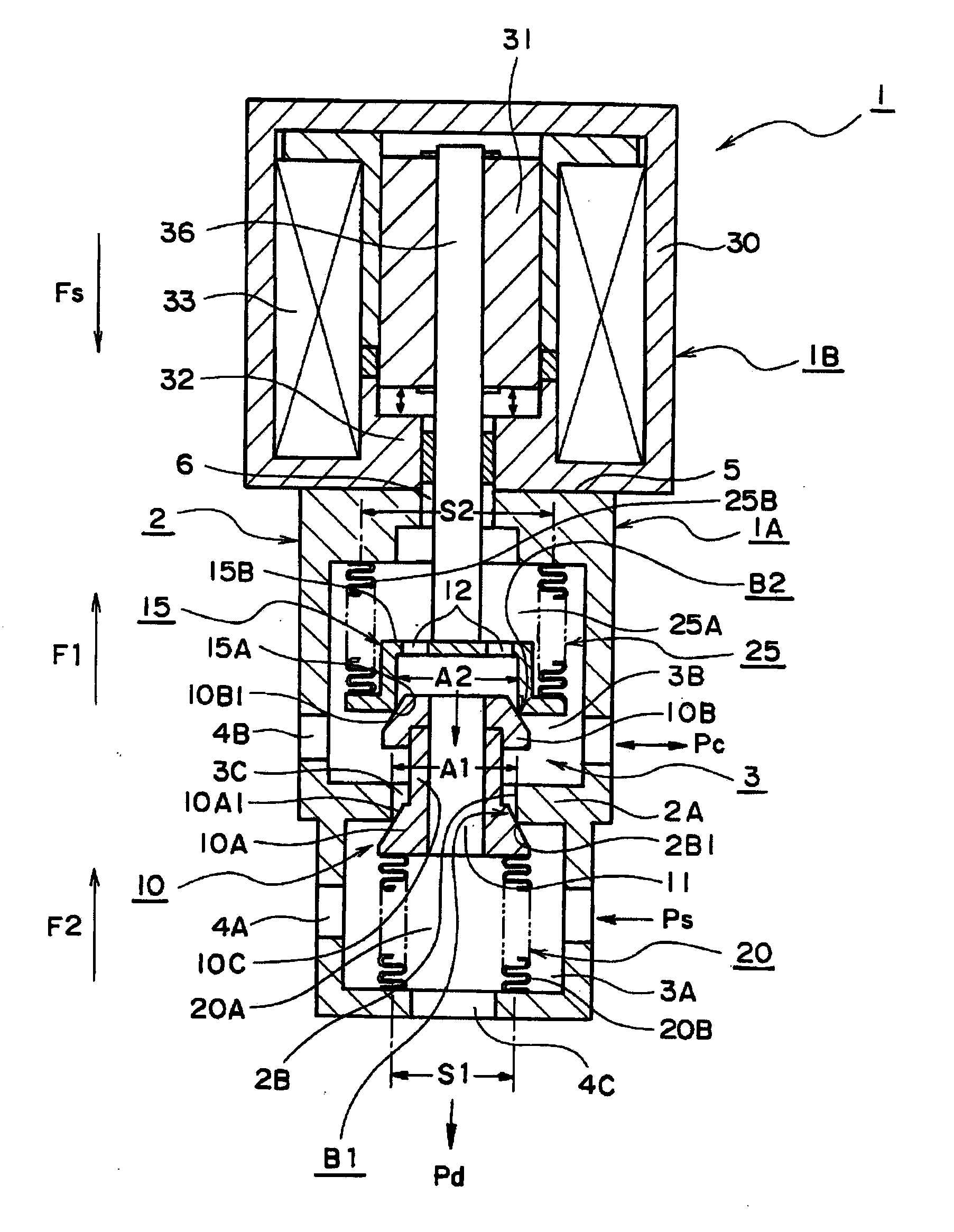
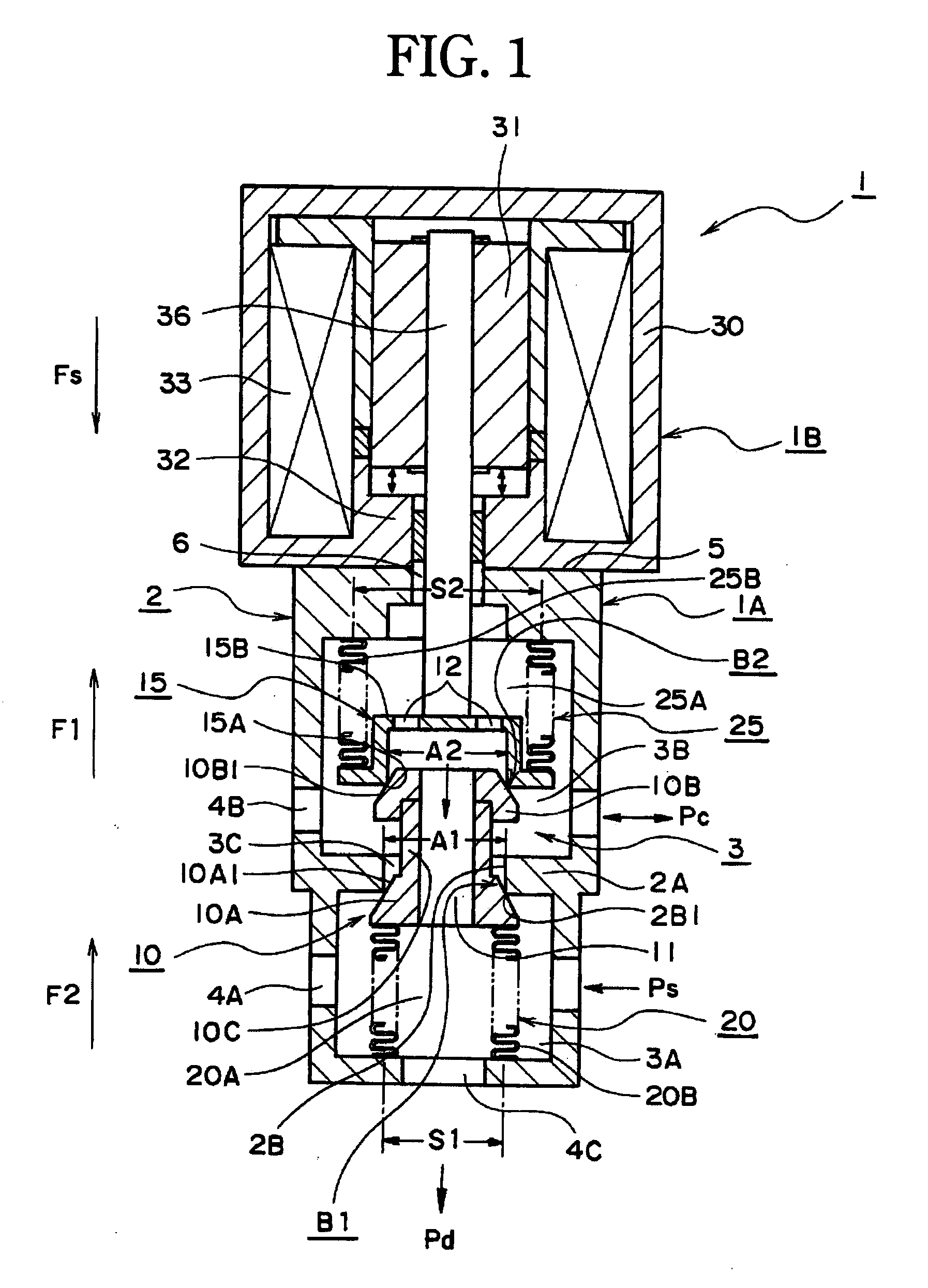
[0033]FIG. 1 is a sectional view of a control valve 1 showing a first embodiment according to the present invention. In FIG. 1, the control valve 1 is a pressure proportional control valve. This control valve 1 is integrally formed with a control valve portion 1A and a solenoid portion 1B. The control valve portion 1A forms an outer frame by a main body 2. The inside of the main body 2 is provided with a valve air chamber 3 having an axially-long shape. The valve air chamber 3 is divided by a partition portion 2A to form a first valve chamber 3A at one side of the partition portion 2A and a second valve chamber 3B at the other side. Further, the partition portion 2A is provided with a valve bore surface 2B in the surrounding surface of a valve bore penetrating the first valve chamber 3A and second valve chamber 3B at its axis. Also, a first valve seating surface 2B1 is formed in a corner portion of an end at the side of the first valve chamber 3A in the valve bore surface 2B. The ma...

embodiment 2

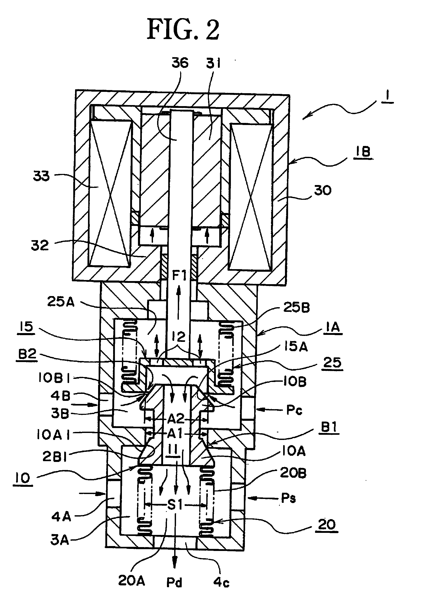
[0062]Next, FIG. 4 is a full sectional view of a control valve 1 of an embodiment 2 according to the present invention. In the control valve 1 of FIG. 4, a solenoid portion 1B is approximately same as in FIG. 1, and a control valve portion 1A is the same invention but is partially changed its structure. Namely, the change in structure of the control valve portion 1A is to provide a first valve chamber 3A of a main body 2 at the side of the solenoid portion 1B and to provide the second valve chamber 3B at the side of a discharge port 4C. Also, in the second valve chamber 3B, a second bellows 25B and a valve seat body 15 are arranged. Further, in the first valve chamber 3A, a first bellows 20B is arranged. Then, a valve body 10 is oppositely placed with respect to FIG. 1 to connect a first valve portion 10A and first bellows 20B, and also, a second poppet valve B2, formed by a second valve portion surface 10B1 of the second valve portion 10B and a second valve seating surface 15A of t...


PUM


Abstract

A control valve where an on/off valve of a valve body has improved response. The control valve has a body having valve seat surfaces placed in first and second valve chambers; a supply port, an output port, and a discharge port of the body; a first pressure-sensing device having a second communication path capable of communicating with the discharge port; the valve body having a first communication path that communicates with the second communication path, having a first valve section surface that forms a first valve seat surface and a poppet, and having a second valve section surface; a valve seat body having a second valve seat surface that forms the second valve section surface of the valve body and a second poppet and also having a first inner path capable of communicating with the first communication path; a second pressure-sensing device connected to the valve seat body in the second valve chamber and having a second inner path capable of communicating with the first inner path; and a solenoid section connected to the valve seat body. The first effective pressure-receiving area of the first pressure-sensing device, the first pressure-receiving area on the inner side of a portion where the first valve seat surface and the first valve section surface are in contact with each other, and the second pressure-receiving area on the inner side of a portion where the second valve seat surface and the second valve section surface are in contact with each other are set to be substantially the same, and the second effective pressure-receiving area of the second pressure-sensing device is set greater than the first effective pressure-receiving area.

Description

TECHNICAL FIELD[0001]The present invention relates to a control valve used for controlling fluid pressure, e.g. controlling pressure of a power transmission device, etc. Particularly, the present invention relates to a control valve to improve malfunction caused by unbalanced working fluid pressure which works on the valve body, malfunction related to sliding resistance when the control valve works, or delay of spring means, etc., related to fast working of the valve body, for pressure proportional control.BACKGROUND ART[0002]As a related art of the present invention, a pressure proportional control valve is known. This pressure proportional control valve is a constitution as shown in FIG. 5 (e.g. Japanese Unexamined Patent Publication No. 2004-197858 (Patent Document 1)). This pressure proportional control valve is a three-way valve used for, for example, a drive unit of an AT (automatic transmission) car and hydraulic control system.[0003]The constitution of this pressure proporti...

Claims


Application Information

Patent Timeline
IPC IPC(8): F16K31/02
CPCF16K31/0655Y10T137/87249Y10T137/87217Y10T137/86919Y10T137/8671
Inventor OKAMOTO, EIJI
Owner EAGLE INDS
Why Eureka
Try Eureka