
Coaxial waveguide electrodeless lamp

a technology of electrodeless lamps and waveguides, which is applied in the direction of gas-filled discharge tubes, magnetic discharge control, structural circuit elements, etc., can solve the problems of limited lifetime, limited range of noble gas and metal halide salts that can be used, and electrode deterioration, so as to achieve the effect of optimizing rf-electrical properties

Active Publication Date: 2010-11-11
TOPANGA USA
View PDF8 Cites 19 Cited by
  • Summary
  • Abstract
  • Description
  • Claims
  • Application Information

AI Technical Summary

Benefits of technology

[0016]In yet another aspect, in the coaxial waveguide electrodeless lamp described above, the lamp is electrically terminated by a load, short, or open circuit to maximize light output.
[0020]In yet another aspect, in the coaxial waveguide electrodeless lamp described above, at least a portion of the gas-fill vessel has a refractory veneer, whereby the refractory veneer prevents diffusion of impurities into the gas-fill vessel.
[0024]In yet another aspect, in the coaxial waveguide electrodeless lamp described above, a portion of the mesh is replaced by a solid metal sheet of substantially the same shape as the portion of the mesh that is replaced. The solid metal sheet is made from a substantially conductive, substantially reflective material. The solid metal sheet acts as a heat sink and a also as a mirror, providing directional light output.
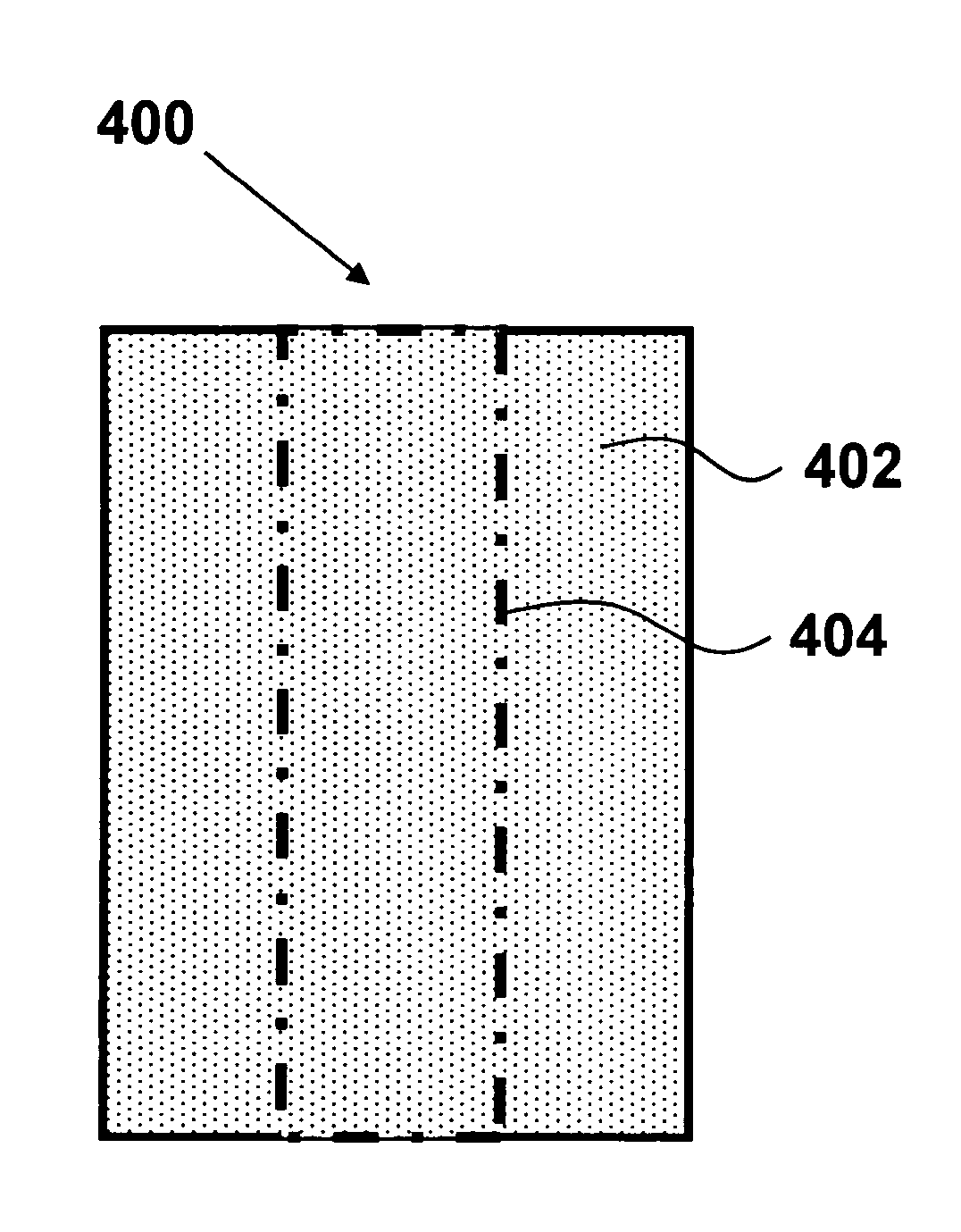
[0033]In yet another aspect, the coaxial waveguide electrodeless lamp described above includes the following further limitations: the coaxial waveguide electrodeless lamp further comprises a dielectric-enhancing layer, the dielectric-enhancing layer being made of a substantially transparent or substantially translucent material with dielectric constant of at least two, and being shaped substantially as an annular cylinder with an inner diameter, an outer diameter, and a long axis substantially parallel to the long axis of the center conductor; the outer diameter of the gas-fill vessel is substantially similar to the inner diameter of the dielectric-enhancing layer, rather than the diameter of the outer conductor; the diameter of the outer conductor is substantially similar to the outer diameter of the dielectric-enhancing layer, rather than the outer diameter of the gas-fill vessel; and the dielectric-enhancing layer fits substantially between the gas-fill vessel and the outer conductor. Thus the dielectric-enhancing layer serves to optimize RF-electrical properties of the coaxial waveguide electrodeless lamp.

Problems solved by technology

However, this arrangement suffers from electrode deterioration due to sputtering of the metal electrodes, and therefore exhibits a limited lifetime.
In addition, the presence of metal electrodes inside the gas-fill vessel limits the range of noble gas and metal halide salt that can be used.
Because electrodes are external to the bulb, these types of bulbs do not have the reliability issues associated with electrode degradation as a result of exposure to plasma and salt material in conventional plasma lamps.
However, the size of the bulb and the electrodes can limit the frequency of the RF source to frequencies in the low gigahertz (GHz) range.
In addition, for longer bulbs the separation between coupling-in electrodes will increase, reducing the strength of the electric field.
Thus, for this type of electrodeless lamp the number of design parameters to optimize the performance and cost of the lamp is limited.
However, in a number of applications the overall size of the lamp that can be used is limited; so the size of the dielectric—and therefore the frequency of operation—will be limited as well.
In addition, scaling the lamp to get a higher light output power is difficult with this design.

Method used


Image

  • Coaxial waveguide electrodeless lamp
  • Coaxial waveguide electrodeless lamp
  • Coaxial waveguide electrodeless lamp

Examples


Embodiment Construction

[0063]The present invention relates to devices and methods for generating light and, more particularly, to the field of electrodeless lamps. Further, the present invention relates to lamps driven by a radio-frequency source without the use of internal electrodes. The following description is presented to enable one of ordinary skill in the art to make and use the invention and to incorporate it in the context of particular applications. Various modifications, as well as a variety of uses in different applications will be readily apparent to those skilled in the art, and the general principles defined herein may be applied to a wide range of embodiments. Thus, the present invention is not intended to be limited to the embodiments presented, but is to be accorded the widest scope consistent with the principles and novel features disclosed herein.

[0064]In the following detailed description, numerous specific details are set forth in order to provide a more thorough understanding of the...


PUM


Abstract

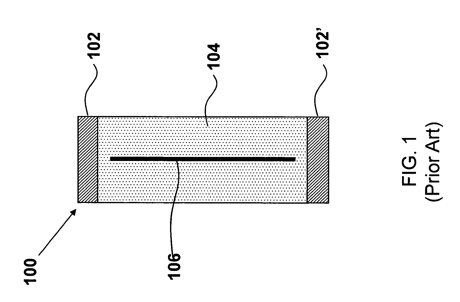
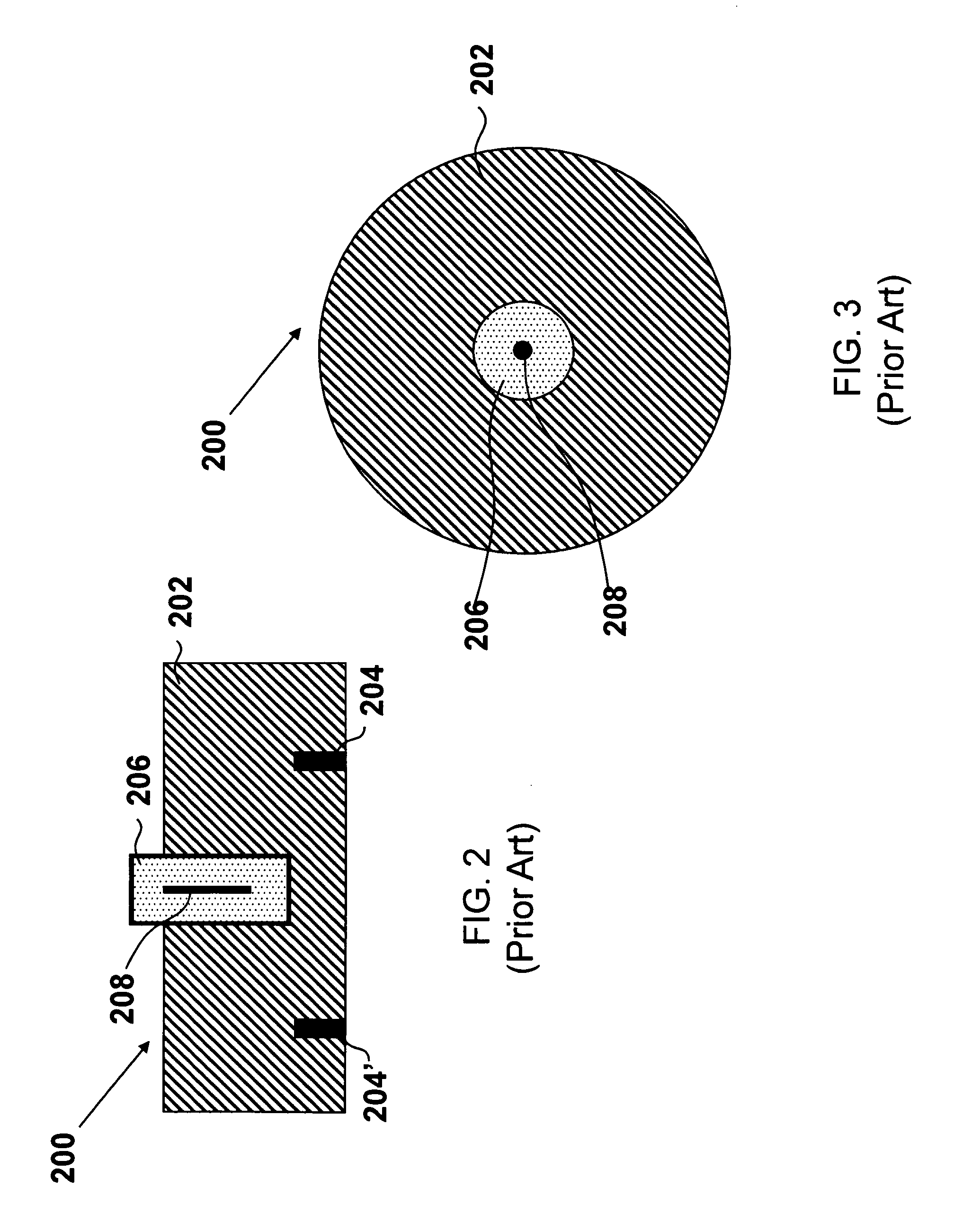
The present invention relates to a coaxial waveguide electrodeless lamp. The lamp is formed in analogy to coaxial waveguide cables, with an outer conductor, a central conductor, and a gas-fill vessel made of dielectric material between the outer conductor and the inner conductor. The gas-fill vessel is substantially hollow and filled with substances that form a plasma and emit light when RF radiation carried by the central conductor and ground conductor interacts with the substances in the gas-fill vessel. The present invention also relates to a leaky waveguide electrodeless lamp. The lamp is formed in analogy to leaky waveguides, with a conductor, a ground conductor, and a gas-fill vessel made of dielectric material butted against the conductor and encompassed by the ground conductor. The leaky waveguide electrodeless lamp emits light from a plasma similar to light-emission action of the coaxial waveguide electrodeless lamp described above.

Description

PRIORITY CLAIM[0001]The present invention is a non-provisional patent application, claiming the benefit of priority of U.S. Provisional Application No. 60 / 786,260, filed on Mar. 28, 2006, entitled “Coaxial Waveguide Electrodeless Lamp.” The present invention further claims priority of U.S. Provisional Application No. 60 / 786,995, filed on Mar. 30, 2006, entitled “Electromagnetic Interference (EMI) Shielding of Electrodeless Lamps Using Cutoff Waveguides.”FIELD OF THE INVENTION[0002]The present invention relates to devices and methods for generating light using electrodeless lamps and, more particularly, to lamps driven by a radio-frequency source without the use of internal electrodes.BACKGROUND OF THE INVENTION[0003]Plasma lamps (such as high intensity discharge (HID) lamps and fluorescent lamps) provide extremely bright, broadband light. Plasma lamps are useful in applications such as projection systems, industrial processing, and general industrial and commercial illumination. Typ...

Claims


Application Information

Patent Timeline
IPC IPC(8): H01J7/46
CPCH01J65/044
Inventor FREDERICK, ESPIAU M.MEHRAN, MATLOUBIANALEXANDRE, DUPUY
Owner TOPANGA USA
Learn More