Inorganic phosphorescent article and method for making same

Inactive Publication Date: 2010-11-11
LACOURSE BRIAN C
View PDF10 Cites 9 Cited by
  • Summary
  • Abstract
  • Description
  • Claims
  • Application Information

AI Technical Summary

Benefits of technology

[0014]In accordance with still another aspect of the present invention there is provided a phosphorescent article having a composite structure including a substrate layer, a reflective layer bonded to the substrate layer and a phosphorescent layer bonded to the reflective layer. The phosphorescent layer comprises photoluminescent phosphor. An optional wear layer may be bonded to the phosphorescent layer. The reflective layer is designed to reflect light emitted from the phosphorescent layer back through the phosphorescent layer providing a more pronounced and sustained phosphorescent effect. Suitable compositions for the reflective layer are those that reflect the wavelength of emitted light from a particular photoluminescent phosphor and include materials such as alumina (Al2O3), titania (TiO2) and mixtures thereof. Each layer can be formed separately and then stacked to form

Problems solved by technology

In many cases electrical power is lost during such an event.
The general use limitations associated with plastics in that they typically degrade when used in prolonged or sustained ultra violet (UV) radiation environments, degrade upon high temperature exposure and have poor wear resistance when subjected to an abrasive environment makes the use of organic plastic matrix photoluminescent articles unsuitable for applications such as emergency signage where fire is involved, outdoor tile subject to intense UV and floor tiling subject to high foot traffic.
While the proposed floor tiles disclosed in the patent to Nolt are an improvement over previous photoluminescent tiles, these tiles are still subject to high cost (due to the amount of photoluminescent material incorporated in the tile body), high wear rates (related to the unfired or conventionally processed tile body) resulting in additional frequent replacement costs and UV degradation due to the thermoplastic resinous binder whi

Method used


Image

  • Inorganic phosphorescent article and method for making same
  • Inorganic phosphorescent article and method for making same
  • Inorganic phosphorescent article and method for making same

Examples


Embodiment Construction

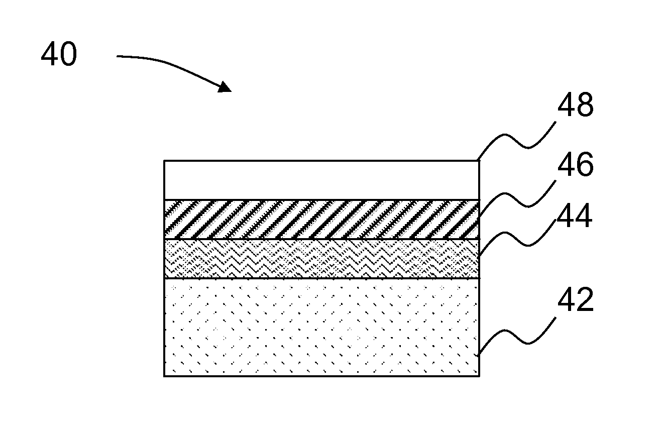
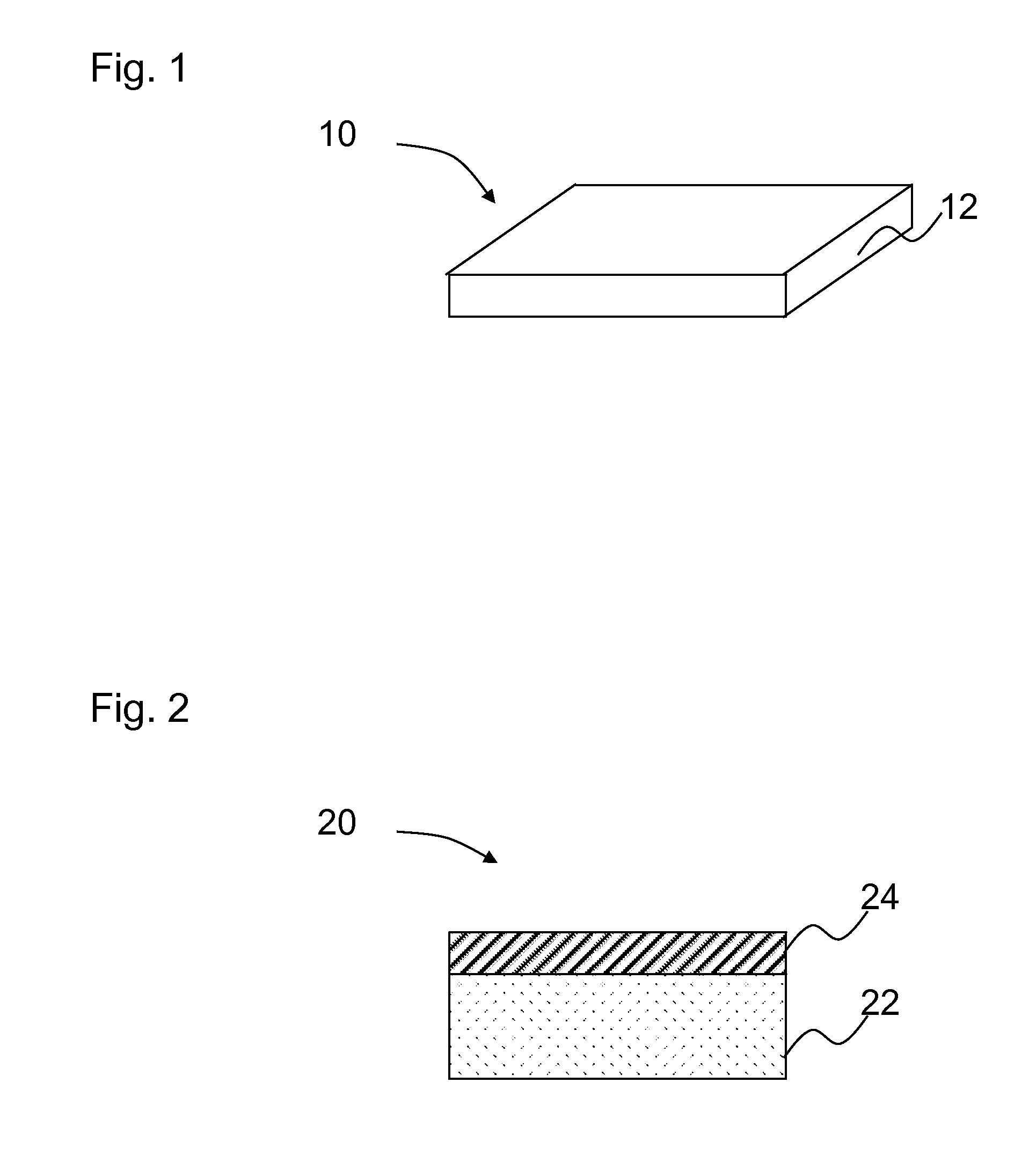
[0025]Generally, an inorganic phosphorescent article of the present invention may be used in any location where it is desirous to have low level lighting such as a part of an emergency lighting system. FIG. 1 generally illustrates an inorganic phosphorescent article 10 of the present invention which includes a formed phosphorescent layer 12. Phosphorescent layer 12 is preferably made where the majority of the layer 12 comprises photoluminescent phosphors powders of rare earth doped alkaline earth aluminates or rare earth doped alkaline earth silicates or zinc sulfide doped with copper or combinations thereof. Some of these rare earth doped alkaline earth aluminates include formulations of strontium aluminate (SrAl2O4), calcium aluminate (CaAl2O4) and barium aluminate (BaAl2O4) or mixed combination. Of the aluminates, strontium aluminate is preferred. Dopants for the aforementioned aluminate formulations include rare earth elements such as europium (Eu), cerium (Ce), praseodymium (Pr...


PUM

PropertyMeasurementUnit
Percent by massaaaaaaaaaa
Electric chargeaaaaaaaaaa

Abstract

An inorganic phosphorescent article having a formed phosphorescent layer where the phosphorescent layer is not mixed with a frit and the majority of the layer comprises photoluminescent phosphors comprising rare earth doped alkaline earth aluminates, rare earth doped alkaline earth silicates, zinc sulfide doped with copper or mixtures thereof. The phosphorescent articles of the present invention may be formed as tile bodies and fired at high temperatures between 1000C and 1600C providing durable ceramic and porcelain tiles suitable for use in emergency lighting flooring systems, aqueous environments such as pools and spas, and outdoor pathway lighting.

Description

[0001]This application claims the benefit of U.S. provisional patent application Ser. No. 61 / 177,097 filed on May 11, 2009.BACKGROUND OF THE INVENTION[0002]Buildings and subway stations display emergency and exit signs in order to direct people to a safe location in the event of a fire, natural disaster, or other event. In many cases electrical power is lost during such an event. If the building goes dark, another means is required to illuminate the emergency signage.[0003]One solution for such a problem is the use of photoluminescent materials. Photo luminescent materials can absorb light from the sun or from man made light sources. The light energy is then released, at a different wavelength. Some photo luminescent materials release the absorbed light energy at a slow rate, such as over several hours. The slow release of absorbed light energy is referred to as phosphorescence. Therefore, photoluminescent materials displaying phosphorescence can be charged with light from the sun o...

Claims


Application Information

Patent Timeline
IPC IPC(8): B32B3/10C09K11/80C09K11/54C09K11/56B32B9/00
CPCC09K11/7706Y10T428/24802C09K11/7734C09K11/7721
Inventor LACOURSE, BRIAN C.
Owner LACOURSE BRIAN C
Why Eureka
Try Eureka